An inverter is used in the system where AC power output is needed.
The input rating of the inverter should never be lower than the total wattage of appliances.
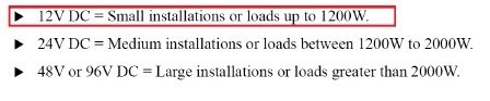
The inverter must have the same nominal voltage as your battery.
For stand-alone systems, the inverter must be large enough to handle the total amount of watts you will be using at one time.
For grid-tie systems or grid-connected systems, the input rating of the inverter should be the same as the PV array rating to allow for safe and efficient operation.
The inverter power should be greater than the load’s total wattage by 25% or 30%.
The inverter’s continuous power = 1.3* total wattage = 1.3153 W = 198.9 W.
If the system has motors, compressors, refrigerators, pumps, and washing machines, we need to make sure that the inverter can withstand the starting current.
The surge power of these devices is found on the label of them.
If you don’t know, you can assume the surge power = 3x – 4x the wattage of these devices.
The inverter surge power = Lamp + Fan + 4 Refrigerators = 378 W.
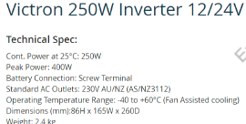
We need an inverter with a continuous power of 198.9 W and a surge power of 378 W.
Step 2: Sizing Inverter
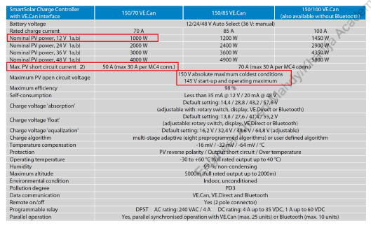
Step 3: Sizing Panels
The total energy required by the loads is 1092 Wh/day.
The total energy needed from panels = total energy * 1.3 (a safety factor to accumulate for all the losses in the PV system in addition to the panels not operating at the optimum conditions) = 1092 Wh * 1.3 = 1419.6 Wh.
The power of panels = 𝑇𝑜𝑡𝑎𝑙 𝑒𝑛𝑒𝑟𝑔𝑦 𝑛𝑒𝑒𝑑𝑒𝑑 𝑝𝑒𝑎𝑘 / 𝑠𝑢𝑛 ℎ𝑜𝑢𝑟𝑠
= 1419.6𝑊ℎ2 ℎ𝑜𝑢𝑟𝑠 = 709.8W.
We will select Sunpower SPR-200-BLK-U.
Number of panels = 𝑇𝑜𝑡𝑎𝑙 𝑝𝑜𝑤𝑒𝑟 / 𝑝𝑜𝑤𝑒𝑟 𝑜𝑓 𝑜𝑛𝑒 𝑝𝑎𝑛𝑒𝑙
=709.8200=3.549 𝑜𝑟 𝑎𝑝𝑝𝑟𝑜𝑥𝑖𝑚𝑎𝑡𝑒𝑙𝑦 4 𝑝𝑎𝑛𝑒𝑙𝑠.
The power of panels = 4 * 200 = 800 W.
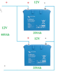
Step 4: Sizing Batteries
Assuming the lowest temperature in the location is -20°C. Then the nominal capacity will be 160 Ah instead of 330 Ah.
The temperature correction coefficient = 160𝐴ℎ / 330𝐴ℎ=0.48.
As the demand for clean and reliable energy continues to rise, solar power has become one of the most popular and accessible renewable energy sources in the world. Whether you live in a city, a village, or a remote area, solar power can offer a sustainable solution to your electricity needs.
In this post, we’ll cover the basics of what solar power is, its key benefits, and the main types of solar systems available today.
🔋 What is Solar Power?
Solar power is the energy we get from the sun. Through the use of solar panels (photovoltaic cells), sunlight is converted into electricity that can be used to power homes, businesses, and even entire communities.
This electricity can be used directly, stored in batteries for later use, or fed into the national grid, depending on the type of solar power system you choose.
✅ Benefits of Solar Energy
Here are some of the major benefits of using solar energy:
Eco-Friendly Solar power is a clean, green source of energy that reduces carbon emissions and pollution.
Saves Money Once installed, solar systems can significantly reduce your electricity bills. In many cases, you can even earn credits through net metering.
Low Maintenance Solar systems require very little maintenance. Most solar panels come with a 20–25 year warranty.
Energy Independence You no longer need to rely solely on utility companies. Solar energy gives you more control over your power source.
Works in Remote Areas Solar is a game-changer for rural and off-grid locations where traditional electricity supply is not available.
☀️ Types of Solar Power Systems (Brief Intro)
There are three main types of solar power systems. Each one is designed to meet different energy needs and budgets:
1. Off-Grid Solar System
Not connected to the utility grid.
Uses batteries to store excess energy for use at night or during cloudy days.
Ideal for remote areas without access to grid electricity.
2. On-Grid (Grid-Tied) Solar System
Connected to the local utility grid.
Any excess power can be sent to the grid (often with credits via net metering).
Suitable for homes and businesses in urban areas.
3. Hybrid Solar System
Combines both off-grid and on-grid features.
Uses batteries for backup and can still send excess energy to the grid.
Offers the flexibility of power storage and grid connection.
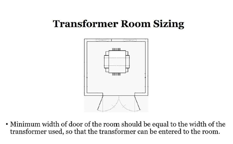
1-The width of the transformer room is equal to or greater than the width of the transformer used for the building.
For more explanation, see the below image:
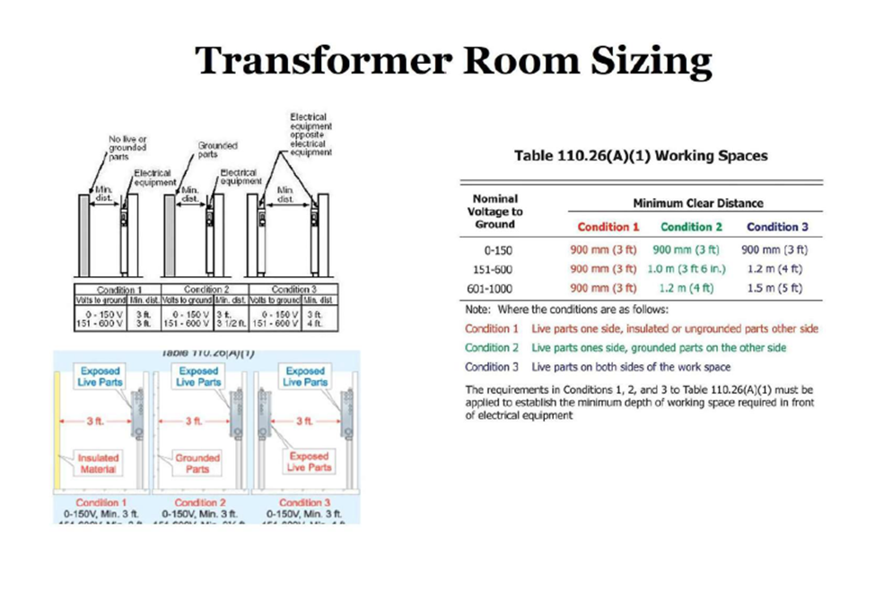
In this image you can see there are three conditions: 1, 2, and 3. let’s explain them one by one.
Condition -1
See the first condition as shown in the image: electrical equipment is installed on one wall; it should be transformers or electrical panels, and the opposite side of the electrical equipment has no live or grounded part; the minimum distance is equal to 3ft or 900 mm, as shown in the image.
Example:
First condition is, distance between transformer and Door.
Condition -2
As shown in the image opposite, the electrical panels have grounded parts, like walls. This means the distance between the panels or transformers is equal to or greater than 3 ft. 6 in. or 1 m.
Example:
The second condition is the distance between the transformer and the wall.
Condition: 3
As shown in the above image, the electrical panel opposite is another panel or live part. This means the distance between the transformer and other live parts, like panels or transformers, is equal to or greater than 4 ft or 1.2 m.
Example:
The third condition is the distance between the transformer and another transformer.
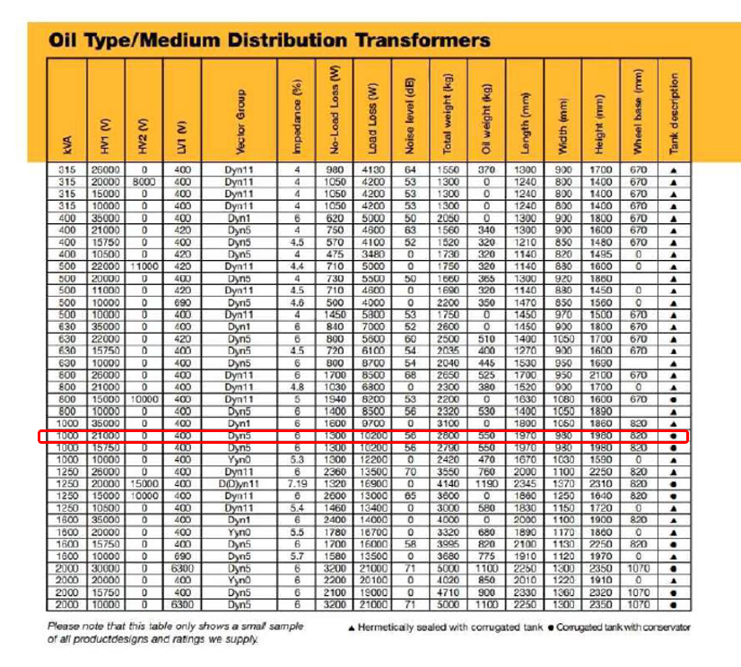
Now I will show you how to calculate the transformer room size from the given transformer size chart:
Practical example:
Given data:
Rating: 1 MVA
Voltage: 21 kV
Length: 1970mm, 1.97m
Width: 980mm, 0.98 m
Calculate transformer room size?
Solution:
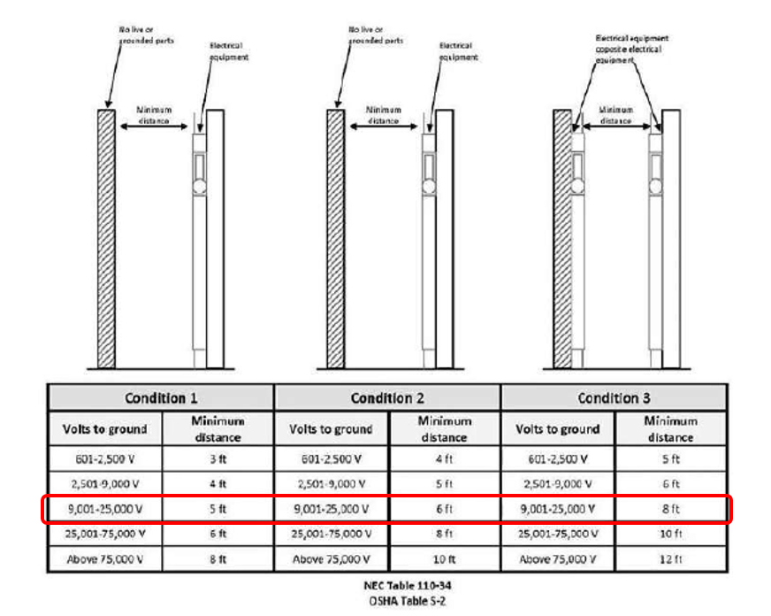
As shown in the above NEC table, our transformer rating is 21 kV. We will select 9 to 25 kV.
Condition-1
The distance between the transformer and door is 5ft, 1.524 m.
Condition-2
The distance between the transformer and wall is 6ft, 1.828
Condition-3
The distance between the transformer and another transformer note (if applicable when there are two transformers in one room).
“Note: This checklist is shared solely for reference and idea generation purposes. Please rephrase or modify the content as needed.”
Checklist for Installation & Testing of Drainage Piping System and Accessories
Checklist for Testing of Drainage Piping System
1- Checklist for Installation & Testing of Drainage Piping System and Accessories
Project Details
Subcontractor: Contractor: Section of Work: Plumbing Location: Level: Work Inspection Request (WIR) No.:
Inspection Stages
Setting Out
Check Layout: Verify layout of the drainage piping system is as per approved shop drawings.
Check Level / Depth: Ensure the level and excavation depth are according to design and approved drawings.
MEP / Civil Coordination
Clearances Check: Confirm that there are no service clashes and required clearance is provided. Verify clearance approval by the consultant’s civil site team.
Installation Inspection
Material Compliance: Ensure all installed materials match the approved material submittals.
Bedding Condition: Check that bedding is free from hard protrusions or large stones and is suitable for pipe laying.
Pipe Size Verification: Confirm that pipe sizes conform to approved drawings.
Slope and Level Check: Verify that the level and slope of the installed pipes meet the approved shop drawing specifications.
Manhole Joint Installation: Ensure push-fit joints are correctly installed for all manhole inlets and outlets.
Road Crossing Pipes: Confirm that pipes crossing roadways are installed according to approved shop drawings.
Leak Testing: All drainage pipes must be tested for leaks.
Pipe End Protection: Check that all open pipe ends are sealed to protect against debris during construction.
Concrete Encasement: Confirm concrete encasement has been applied where required.
Backfilling Release: Ensure pipes are approved and released for backfilling.
Backfilling Execution: Check that backfilling is done in accordance with the approved drawings and specifications.
Final Approvals
For Subcontractor QA/QC:
Name:
Signature:
Date:
For Contractor QA/QC:
Name:
Signature:
Date:
For Consultant Representative:
Name:
Signature:
Date:
2- Checklist for Testing of Drainage Piping System
Form No.: Revision No.: 0 Page: 1 of 1
Project Information
Subcontractor: Contractor: Section of Work: Plumbing Location: Level: Work Inspection Request (WIR) No.:
Inspection & Testing Checklist
Stage-wise Verification
Stage:
Item:
Checked by (Subcontractor):
Checked by (Contractor):
Checked by (Consultant):
Date:
Test Details
Piping System:
Test Pressure:
Actual Pressure:
Date of Test:
Duration of Test:
Testing Fluid/Gas:
Start Time:
Finish Time:
Pressure Gauge Number:
Calibration Due Date:
Remarks
(Insert any additional observations or issues noted during the test)
Test Results
☐ No leaks were observed during the test duration. Test results are acceptable. ☐ Test results are not acceptable. Rectify leaks and retest.
1.1 This fire alarm testing method statement outlines the step-by-step process for inspecting and testing the fire alarm system at this project site.
1.2 The contractor may further enhance or expand upon these guidelines, subject to agreement with the Project M&E Engineer and Independent Testing and Commissioning Engineer.
1.3 The primary goal of this procedure is to verify that the fire alarm system’s installation and performance align with the M&E design intent.
1.4 The contractor must become familiar with the existing system’s operation, including the cause and effect scenarios. Upon completing the commissioning, the contractor will perform comprehensive cause and effect testing on the new fire alarm installation to ensure compatibility and consistency with the existing configuration.
2. Test Instruments / Tools Required
2.1 All testing instruments must have a valid calibration certificate (at least 6 months remaining) traceable to international standards.
2.2 Instruments should be suitable for the expected test parameters and provide accurate readings, ideally at their mid-range scale.
2.3 The following tools and equipment are required for fire alarm system testing:
Calibrated Multimeter
Aerosol Smoke Canisters
Heat Source
Walkie Talkies
3. Reference Standards
3.1 The testing procedure adheres to the following British Standards:
BS 6266:2002 – Code of Practice for Fire Protection for Electronic Equipment Installations
BS 5839:2002 – Code of Practice for Fire Detection and Alarm Systems for Buildings
All testing and commissioning activities must comply with these standards.
4. Test Procedures
Before testing begins, ensure the following:
4.1 Verify correct placement and installation of device housings and components. 4.2 Confirm that appropriate cable types are used. 4.3 Ensure all high and low voltage cables have passed electrical testing, and power (AC/DC) is available at correct voltages.
Note: Never connect devices until wiring tests are approved to avoid potential damage.
4.4 Confirm proper labeling of all system components per design specifications. 4.5 Verify device numbering and alarm message descriptions match the latest architectural layout or room names. 4.6 Perform insulation resistance tests, polarity checks, and loop resistance measurements. 4.7 Measure addressable circuit capacitance and inductance where applicable. 4.8 Confirm all equipment (detectors, sounders, etc.) is properly installed per manufacturer instructions. 4.9 Check suppressors and polarizing diodes on electro-mechanical sounders. 4.10 Ensure short circuit isolators are installed at specified intervals. 4.11 Confirm battery sizing by recording voltage and current data. Simulate standby operation and record performance.
5. Test Execution
Before starting, print the list of all addressable devices and confirm:
Devices are installed and in normal status
No devices are isolated or malfunctioning
5.1 Functional Testing:
5.1.1 Test call points with a key or by breaking glass. 5.1.2 Use aerosol smoke to test smoke detectors. 5.1.3 Apply heat (e.g., hair dryer) to test heat detectors without damaging components. 5.1.4 Confirm proper operation of all input/output devices.
5.2 At Each Detector:
5.2.1 Ensure LED lights up during detection.
5.3 At the Fire Alarm Control Panel:
5.3.1 RED fire lamp should light. 5.3.2 Internal sounder must activate. 5.3.3 Relevant fire zone must be indicated. 5.3.4 Correct text message should display and print. 5.3.5 Appropriate sounders should activate. 5.3.6 Switching relays should change state.
5.4 After Alarm is Muted:
5.4.1 Internal sounder remains audible. 5.4.2 Fire zone still indicated. 5.4.3 ‘Fire’ lamp stays illuminated.
5.5 Fault Testing:
5.5.1 Remove each detector; verify ‘Fault’ lamp and sounder activate. 5.5.2 Ensure fault message displays and prints. 5.5.3 Replace components and reset the system to confirm restoration.
5.6 Sounder Walk Test:
5.6.1 Program panel for walk test. 5.6.2 Walk the site and confirm sounder operation. 5.6.3 Reset panel to normal after test.
Alternatively, activate alarm in ‘Test’ mode and verify sounders.
5.7 Audibility Test:
5.7.1 Activate alarms; use calibrated sound level meter. 5.7.2 Acceptable sound level is minimum 65dB(A) or 5dB(A) above ambient noise sustained for over 30 seconds. 5.7.3 Repeat test during full occupancy if initially unoccupied. 5.7.4 Use BS5969 Type 2 compliant meter, slow response, A-weighted.
5.8 Short Circuit Testing:
Introduce shorts at intervals to verify isolators and ensure fire system functionality is retained, except at the faulted segment.
5.9 Battery Testing:
Measure standby and alarm currents using multimeter across fuse terminals.
Isolate mains, record performance in both standby and alarm modes.
Simulate a full mains failure and verify backup battery operation during full alarm for required duration.
6. Fire Dampers
6.1 The responsible trade contractor shall submit a comprehensive fire damper schedule including reference numbers, locations, type, and size (base build and fit-out).
6.2 The schedule must confirm that drop tests were completed and that dampers are accessible and resettable. Upon confirmation, 100% of dampers will be witnessed by the Independent Testing and Commissioning Engineer, and subsequently reviewed by the Fire Marshal.
7. Test Record Sheets
The following documentation must be completed and submitted:
This guide provides a complete and professional procedure for commissioning a Building Management System (BMS), including safety precautions, integration checks, and testing requirements.
🧷 Safety Preparations
Ensure engineers and technicians wear appropriate PPE.
Clear the area around the BMS panel to allow easy and safe access.
Unlock and open the BMS panel using the provided keys.
Verify that there is no power in the system using a multimeter.
🔧 Cable and Connection Inspection
Check that all terminated cables are tightly secured and no conductors are exposed.
Confirm cable terminations are as per the wiring diagram and cable schedule.
Perform the following safety checks:
Line-to-neutral continuity
Earth connection verification
Enclosure body grounding
Transformer earthing confirmation
🔗 Integration Verification
Verify all integration cables are properly connected:
System
Protocol
Cable Type
Fire Alarm System
BACnet/IP
CAT-6
Lighting Control
BACnet/IP
CAT-6
Water Meters
Modbus/RTU
Serial
Multifunction Meters
Modbus/RTU
Serial
VRV System
BACnet/IP
CAT-6
Confirm integrated systems are configured by coordinating with the BMS supplier.
For IP-based connections, ensure suppliers use BMS-designated IP ranges.
All integrated systems must allow BMS discovery of their data points.
⚡ Power Supply & Breaker Verification
Ensure all secondary breakers and fuses are in the OFF position.
Measure incoming power (L-L and L-N) using a multimeter; confirm 380V/3PH/60Hz as per drawings.
After verification, switch ON the MCCB.
Measure voltage post-MCCB and record.
Sequentially activate breakers/fuses and confirm power output.
💻 DDC & Software Commissioning
Once power is verified, the panel is ready for system integration.
Connect a laptop to the DDC and enable communication.
Launch commissioning software and enter the third-party integration parameters.
Discover the integrated system’s data points.
If successful, define and store them in the BMS controller.
Validate values against actual system data.
For meters, verify values from the physical display.
📊 HMI & Finalization
Check the HMI screen to ensure all signals and values are correctly displayed. Create users with different administrative roles. Upload and verify graphics on EWS and OWS at the Control & Admin buildings.
Secure and lock the BMS panel.
Conduct final housekeeping.
Inform the contractor/consultant that the system is ready for handover.
This method statement outlines the comprehensive procedure for the testing and commissioning of the Building Management System (BMS). The main objective is to confirm that the system installation aligns with the project’s design intent and performs as specified.
The contractor shall enhance this baseline procedure by proposing any additional tests, subject to approval by the Project M&E Engineer and Independent Testing & Commissioning Engineer.
2. Test Instruments and Tools Required
All testing tools must come with current calibration certificates traceable to international standards (valid for at least six months). The instruments must be capable of accurate readings within the mid-range of their operating range.
Essential Testing Tools:
Calibrated multi-meters
General tightening or fastening tools (screwdrivers, battery drills, spanners etc.)
Calibrated RH / temperature / Pressure measuring instruments
Test pens.
Walkie-talkies
Test Jumper Cable.
Freeze Spray
Heater (Hair Dryer)
Cold steam generator
Torchlight
3. Reference Standards
The following industry standards have been followed in developing this BMS testing methodology:
CIBSE Guide H (2000) – Building Control Systems
BSRIA AH 2/92 – Commissioning of BEMS
CIBSE Commissioning Code C (2001) – Automatic Controls
4. BMS Testing Procedure
Before beginning any testing, ensure pre-commissioning and startup checklists are completed. Use the standardized Template Test Sheets for recording all steps and outcomes.
4.1 Pre-Commissioning Checks
Verify that the enclosure is not mounted to a vibrating surface.
Verify that proper wiring installations have been completed by the sub-contractor.
Check all point and trunk wiring for shorts, grounds and induced/stray voltages. Also verify all terminated according to as-built drawings.
Verify that the correct point modules have been inserted to the proper termination address keys have been placed in proper slots. Install corresponding module labels.
Verify that required LAN trunk wires have been wired to the connectors and placed on the temporary cover that wraps around the mounting rails, M-Bus rails and C-Bus at the bottom of the backplane. Verify proper PMD and LAN trunk terminations and proper shielding.
Verify that the power module had been installed as per required.
Verify that the open processor has been installed as per required.
Verify that the MBC has been powered with the proper voltage.
Using the hyper terminal to configure the open processor as required. Verify that the open processor status LED flashes.
Logon to the BMS System Database Server and upload the MBC database. Upon completion, the insight workstation will be able to monitor the status.
Fill-up the DDC information table so that all parameter have been captured.
Upon completion of these procedures, point to point check-out may commence.
4.2 DDC Information Table
Fill in key system parameters like:
MBC name, location, and address
Firmware and baud rates
M-Bus enabled status
Battery check results
4.3 DDC Startup Checklist
Ensure complete system power-up and connection:
UPS, Database Servers, Trunk Interfaces
Load BMS software and verify communication with MBCs
Perform database upload and integrity check
4.4 I/O Point Testing
Validate field equipment values against BMS readings. Document each test with:
Point Name, Description
Analogue & Digital Readings (Field vs. BMS)
Acknowledgment
4.5 Status Point Testing
Simulate ON/OFF/TRIP feedbacks and verify BMS reflects actual changes. Attach trend logs and status reports.
4.6 Command Point Testing
Issue ON/OFF commands from the BMS and verify successful communication and action at field devices.
4.7 Alarm Point Testing
Simulate alarm conditions to confirm:
Alarm messages display accurately
Alarm logs and trend reports are generated
Message clarity and fault tracing are accurate
4.8 Sensor Calibration
Calibrate and offset sensors using certified devices:
Temperature: 22˚C ±1˚C
Humidity: 50% ±5%RH
Pressure: ±5%
Document measured vs. BMS values and apply required offsets. Recheck and log the calibration results.
4.9 Water Leak Detection Interface
Test alarm triggers via controlled water exposure and verify:
Alarm accuracy and description
Auto-reset functionality
Cable fault recognition
Shutdown response (if applicable)
4.10 Fire System Interface Testing
Ensure all fire alarm signals are accurately reflected in the BMS, including:
Normal/Alarm states
Fault triggers
Power failures
Clear alarm descriptions
4.11 High-Level Interface Testing
Verify protocol handshake and real-time status/alarm data between BMS and third-party systems. Cross-check LCD display data with BMS screens.
4.12 Control Valve Testing (AHU / FCU)
Test modulating valve response to temperature changes and direct commands (0%, 50%, 100% open). Verify valve positions match command inputs.
Inspect that all wiring installation have been done properly according to the specification.
Setup trending for the points that needed to be tested.
Ensure the device being controlled is active.
Ensure local physical state and BMS Screen AHU/FCU On control, match.
Command the AHU/FCU control setpoint higher than the current temperature reading.
Valve will be modulated to satisfy the new setpoint. Verify the valve position to match.
Command the AHU/FCU control setpoint lower than the current temperature reading.
Valve will be modulated to satisfy the new setpoint. Verify the valve position to match.
Command the control valve to 50% open and observe in the field the same.
Command the control valve to 100% open and observe in the field the same.
Command the valve to 0% open and observe that the valve fully closes in the field
Print out the trend report and attached to this test & commissioning report.
Metering (Electricity and Water) Testing
Perform verification of kWh / Water volume meters data collection and time-based accumulation. Ensure pulses are registering on “Inst Value” on BMS Screen.
For kWh / Water volume (where applicable) meters, compare the local instantaneous value from metering instrumentation against the BMS Screen. Ensure these two figures correlate within an accuracy of less than +/- 5%.
Enable the Peak Reset for the applicable meter under test. Ensure Peak Value resets to current instantaneous value. Ensure “Peak Reset” point automatically returns to disable.
Ensure Trending verifies correct operation of all time-based consumption/instantaneous BMS data points below:
ACD=Actual Consumption Day
ACM=Actual Consumption Month
ACY=Actual Consumption Year
PCD=Previous Consumption Day
PCM=Previous Consumption Month
PCY=Previous Consumption Year
Peak Value
Instantaneous Value
4.13 Metering System Testing (Power & Water)
Confirm accuracy within ±5% between local meter readings and BMS screen values. Validate:
Peak reset function
Time-based accumulations (Daily/Monthly/Yearly)
Instantaneous readings
5. Functional Testing
Ensure:
All devices are powered, configured, and fully tested
Communication is stable across all networks
Operational logic is validated under typical and emergency scenarios
All the BMS Sub-Systems and associated devices are powered up, fully configured and have passed 100% of all relevant BMS Interface tests
All the BMS and ACS panels powered up, fully configured and passed supplier diagnostics.
Check the BMS database and graphics are complete to facilitate these tests.
Ensure the Trend Setup for the equipment under test has been completed.
Confirm the control logic diagram has been approved by the Consultant.
Initiate a scheduled start-up and shutdown sequence for each piece of equipment or system and observe the equipment / system for the correct operation.
Initiate a scheduled changeover of equipment if applicable on a daily or weekly schedule.
Confirm the required schedule start and stop times and enter into system
Restart the equipment, initiate each type of alarm in the field and confirm the correct operation / changeover of system or equipment in the field.
Confirm that the correct alarm message has been raised and issued by SMS / pager system.
Confirm if “mismatch” alarm is raised if command is different from status.
Follow logic chart through for all alarms / failure combinations to confirm the correct operation of the equipment or system
Check all graphic representations display correctly eg alarm points turn red on graphic, and that all equipment references are correct.
Print out alarm report for the equipment that has just been completed. Attach to Record sheet.
Print out the trend report and attached to this test & commissioning report.
6. Fire Shutdown Testing
Simulate fire alarms to verify automatic shutdown sequences and proper BMS response across all connected systems.
During Fire inspection verification ensure that when General Fire Alarm is active (“In Alarm”)
The Supply and Exhaust Fans assume the correct operational mode required by Local Fire Authority.
When the General Fire Alarm clears (“Return to Normal”) ensure the fans (SF/EF) maintain the their “Fire Alarm” running mode.
Ensure after “Fire Reset” is enabled that all fans assume “Normal” operation mode.
Ensure “Fire Reset” point automatically returns to disable.
Print out alarm report for the equipment that has just been completed. Attach to Record sheet.
Compile results together with Engineers Report Sheet and Fire test sheets confirming all times and durations of tests match.
7. Test Record Documentation
All trend reports, alarm logs, and test results must be printed and attached to the commissioning report for submission and approval.
Test Sheets as required fro Template Test Sheet Documents
This document outlines the procedures for the installation, testing, and commissioning of firefighting equipment as per project specifications, approved shop drawings, and safety standards.
📦 2. Scope
Covers the complete lifecycle of firefighting equipment, including:
Supply
Installation
Testing
Commissioning
All activities shall comply with the manufacturer’s guidelines and project-specific technical documents.
📚 3. References
ISO 9001:2008
Project Quality Plan (PQP)
Project HSE Plan
Latest approved shop drawings
Manufacturer’s manuals and material submittals
📖 4. Abbreviations
PQP: Project Quality Plan
HSE: Health, Safety & Environment
QA/QC: Quality Assurance / Quality Control
ITP: Inspection & Test Plan
MIR/WIR: Material/Work Inspection Request
UPVC / HDPE / PEX / G.I. Pipes: Pipe materials used in FF systems
👷 5. Responsibilities
👨💼 Project Manager
Ensure timely progress and material availability
Maintain quality and safety in coordination with QA/QC & HSE
🏗️ Construction Manager
Supervise worksite activities
Coordinate inspections and approvals
🧑💻 Site Engineer
Implement approved method statements
Monitor progress and coordinate inspections
🛠️ QA/QC Engineer
Ensure compliance with drawings/specifications
Raise MIRs/WIRs and conduct required tests
🧰 Site Foreman
Oversee daily tasks and distribute resources
Report progress and issues
🦺 HSE Officer
Enforce safety protocols
Conduct safety briefings and ensure proper PPE use
🗃️ Store Keeper
Manage delivery and storage of firefighting materials
Coordinate with QA/QC for material verification
🛠️ 6. Tools & Equipment
Tool Box & Measuring Tape
Electric Drill & Threading Machine
Pipe Cutting & Grinding Machines
Torque Wrench & Pressure Gauge
Mobile Scaffold & Staging Platforms
Safety PPE, Warning Signboards
🚧 7. Installation Procedure
✅ 7.1 General Requirements
All equipment must be inspected via MIR prior to installation
Qualified personnel must perform tasks per approved drawings
🚛 7.2 Delivery & Transport
Equipment should arrive in proper packaging
Handle with care to avoid scratches or dents
🏠 7.3 Storage
Store in dry, protected areas
Keep items in original packaging until needed
🔩 7.4 Installation Sequence
⚠️ Safety First
Conduct toolbox talks
Use PPE and follow site-specific HSE rules
Display caution signage during works
🔧 Pre-Installation Checklist
Verify civil clearance and approved shop drawings
Ensure no clashes with other services
Access areas must be cleared and safe
🧯 Fire Hose Reel & Cabinet Installation
Confirm manufacturer’s specs and accessories
Mark mounting points precisely
Install with supports (steel brackets if needed)
Connect piping and verify valve accessibility
Conduct inspections via WIR after installation
🧨 Fire Extinguisher Installation
Follow approved locations on shop drawings
Install mounting brackets correctly
Use appropriate extinguisher types (e.g., Dry Powder, CO2)
Raise inspection request for consultant approval
✅ 7.5 Testing & Commissioning
🔍 Visual Inspection
Inspect hoses, nozzles, and piping
Ensure full reach, no tears, proper rewind
🧪 Testing Process
Operate hose reels for smooth extension and rewind
Check valve leaks (≤5ml in 5 minutes)
Ensure minimum flow rate (≥0.33 L/sec)
⚙️ Commissioning – Fire Hose Equipment
Verify hose racks swing and hose extends freely
Confirm nozzle functions properly
Ensure cabinet is accessible, locks function, glazing intact