Contents
- Introduction
- Test Instruments/Tools Required
- Reference Standards
- Test Procedures
- Test Execution
- Fire Dampers
- Test Record Sheets
1. Introduction

1.1 This fire alarm testing method statement outlines the step-by-step process for inspecting and testing the fire alarm system at this project site.
1.2 The contractor may further enhance or expand upon these guidelines, subject to agreement with the Project M&E Engineer and Independent Testing and Commissioning Engineer.
1.3 The primary goal of this procedure is to verify that the fire alarm system’s installation and performance align with the M&E design intent.
1.4 The contractor must become familiar with the existing system’s operation, including the cause and effect scenarios. Upon completing the commissioning, the contractor will perform comprehensive cause and effect testing on the new fire alarm installation to ensure compatibility and consistency with the existing configuration.
2. Test Instruments / Tools Required
2.1 All testing instruments must have a valid calibration certificate (at least 6 months remaining) traceable to international standards.
2.2 Instruments should be suitable for the expected test parameters and provide accurate readings, ideally at their mid-range scale.
2.3 The following tools and equipment are required for fire alarm system testing:
- Calibrated Multimeter
- Aerosol Smoke Canisters
- Heat Source
- Walkie Talkies

3. Reference Standards
3.1 The testing procedure adheres to the following British Standards:
- BS 6266:2002 – Code of Practice for Fire Protection for Electronic Equipment Installations
- BS 5839:2002 – Code of Practice for Fire Detection and Alarm Systems for Buildings
All testing and commissioning activities must comply with these standards.
4. Test Procedures
Before testing begins, ensure the following:
4.1 Verify correct placement and installation of device housings and components.
4.2 Confirm that appropriate cable types are used.
4.3 Ensure all high and low voltage cables have passed electrical testing, and power (AC/DC) is available at correct voltages.
Note: Never connect devices until wiring tests are approved to avoid potential damage.
4.4 Confirm proper labeling of all system components per design specifications.
4.5 Verify device numbering and alarm message descriptions match the latest architectural layout or room names.
4.6 Perform insulation resistance tests, polarity checks, and loop resistance measurements.
4.7 Measure addressable circuit capacitance and inductance where applicable.
4.8 Confirm all equipment (detectors, sounders, etc.) is properly installed per manufacturer instructions.
4.9 Check suppressors and polarizing diodes on electro-mechanical sounders.
4.10 Ensure short circuit isolators are installed at specified intervals.
4.11 Confirm battery sizing by recording voltage and current data. Simulate standby operation and record performance.
5. Test Execution
Before starting, print the list of all addressable devices and confirm:
- Devices are installed and in normal status
- No devices are isolated or malfunctioning
5.1 Functional Testing:
5.1.1 Test call points with a key or by breaking glass.
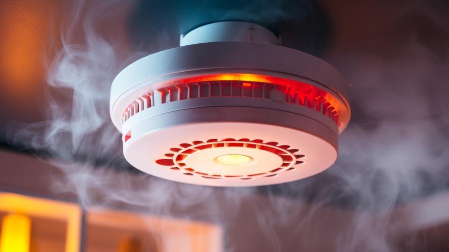
5.1.2 Use aerosol smoke to test smoke detectors.
5.1.3 Apply heat (e.g., hair dryer) to test heat detectors without damaging components.
5.1.4 Confirm proper operation of all input/output devices.
5.2 At Each Detector:
5.2.1 Ensure LED lights up during detection.
5.3 At the Fire Alarm Control Panel:
5.3.1 RED fire lamp should light.
5.3.2 Internal sounder must activate.
5.3.3 Relevant fire zone must be indicated.
5.3.4 Correct text message should display and print.
5.3.5 Appropriate sounders should activate.
5.3.6 Switching relays should change state.
5.4 After Alarm is Muted:
5.4.1 Internal sounder remains audible.
5.4.2 Fire zone still indicated.
5.4.3 ‘Fire’ lamp stays illuminated.
5.5 Fault Testing:
5.5.1 Remove each detector; verify ‘Fault’ lamp and sounder activate.
5.5.2 Ensure fault message displays and prints.
5.5.3 Replace components and reset the system to confirm restoration.
5.6 Sounder Walk Test:
5.6.1 Program panel for walk test.
5.6.2 Walk the site and confirm sounder operation.
5.6.3 Reset panel to normal after test.
Alternatively, activate alarm in ‘Test’ mode and verify sounders.
5.7 Audibility Test:
5.7.1 Activate alarms; use calibrated sound level meter.
5.7.2 Acceptable sound level is minimum 65dB(A) or 5dB(A) above ambient noise sustained for over 30 seconds.
5.7.3 Repeat test during full occupancy if initially unoccupied.
5.7.4 Use BS5969 Type 2 compliant meter, slow response, A-weighted.
5.8 Short Circuit Testing:
Introduce shorts at intervals to verify isolators and ensure fire system functionality is retained, except at the faulted segment.
5.9 Battery Testing:
- Measure standby and alarm currents using multimeter across fuse terminals.
- Isolate mains, record performance in both standby and alarm modes.
- Simulate a full mains failure and verify backup battery operation during full alarm for required duration.
6. Fire Dampers
6.1 The responsible trade contractor shall submit a comprehensive fire damper schedule including reference numbers, locations, type, and size (base build and fit-out).
6.2 The schedule must confirm that drop tests were completed and that dampers are accessible and resettable. Upon confirmation, 100% of dampers will be witnessed by the Independent Testing and Commissioning Engineer, and subsequently reviewed by the Fire Marshal.
7. Test Record Sheets
The following documentation must be completed and submitted:
- Cable Test Sheets
- Marked-Up Floor Layout Drawings
- Complete Device List with Alarm Messages
- Fire Alarm Panel Test Result Printouts
Add a Comment