What is Building Services Planning Manual

Engineering Drawing Submittal & Approval

 Drawing Submittal & Approval

Method Statement (MS) Submittal & Approval

Mechanical System (HVAC)

Electrical System

Plumbing and Fire Fighting System

Construction

Project Milestone Requirements

Mechanical System

Electrical System

Plumbing System

Fire Fighting System

Add a heading (2)

🔧 Method Statement for the Supply & Installation of Plumbing Fixtures, Sanitary Wares & Accessories

📌 1.0 Purpose – Ensuring Quality Installation of Sanitary Fixtures

This method statement is applicable for the supply and installation of plumbing fixtures, sanitary wares, and accessories as detailed in the approved drainage shop drawings.


📦 2.0 Scope – Complete Plumbing Fixture and Sanitary Ware Installation

Covers all activities related to supply, installation, and inspection of plumbing fixtures and sanitary accessories in line with project requirements and approved shop drawings.


📚 3.0 References – Documents Guiding Installation Quality

  • Latest Approved Shop Drawings
  • Project Specifications
  • Project Quality Plan (PQP)
  • Project HSE Plan
  • Material Approval Request (MAR) for Sanitary Wares

📖 4.0 Definitions – Abbreviations & Key Terms Explained

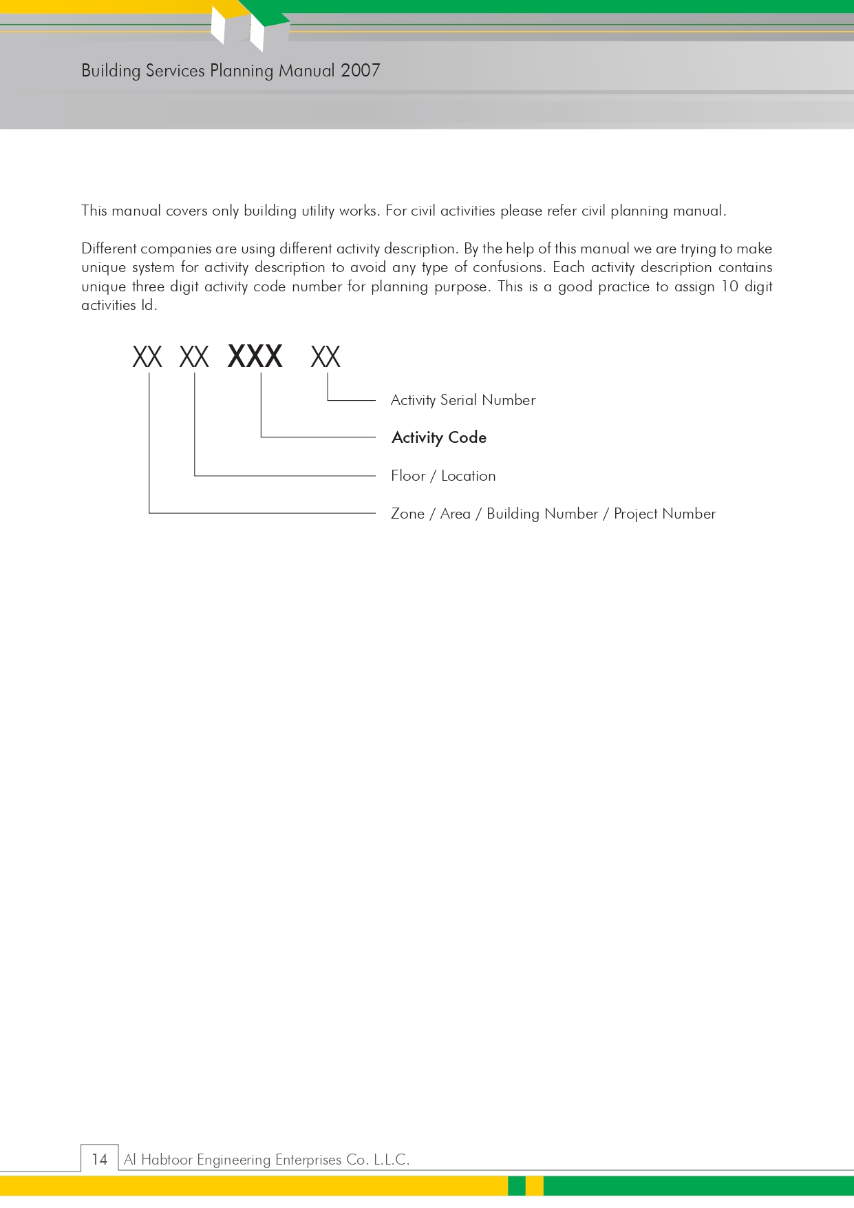
A comprehensive list of abbreviations such as PQP, PSP, HSE, ITP, WIR, MIR, MAR, UPVC, HDPE, and more.


👷 5.0 Responsibilities – Team Roles in Sanitary Ware Installation

🔹 5.1 Project Manager

Focuses on project timelines, equipment readiness, and coordination with QA/QC and HSE teams.

🔹 5.2 Construction Manager

Manages daily site operations, approvals, and coordination with site teams.

🔹 5.3 Site Engineer

Implements drawings/specifications, oversees progress, coordinates inspections and safety.

🔹 5.4 QA/QC Engineer

Ensures compliance, raises WIR/MIRs, conducts inspections, and assists consultants.

🔹 5.5 Site Foreman

Manages labor and resource distribution while ensuring daily progress.

🔹 5.6 Safety Officer

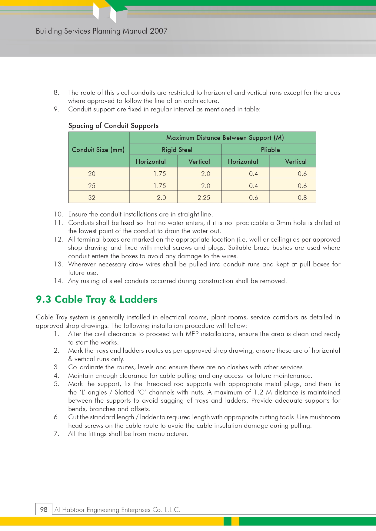
Implements and monitors safety protocols, PPE usage, and safe access.

🔹 5.7 Store Keeper

Ensures proper material handling, safe storage, and coordination during delivery.


🧰 6.0 Tools & Equipment – Essential Gear for Installation

Includes: Tool box, pipe wrench, measuring tape, spirit level, electric drill, solvent cement, welding machine (if required), and ladders.


🛠️ 7.0 Installation Procedure – Step-by-Step Plumbing Installation Guide

7.1 General Requirements

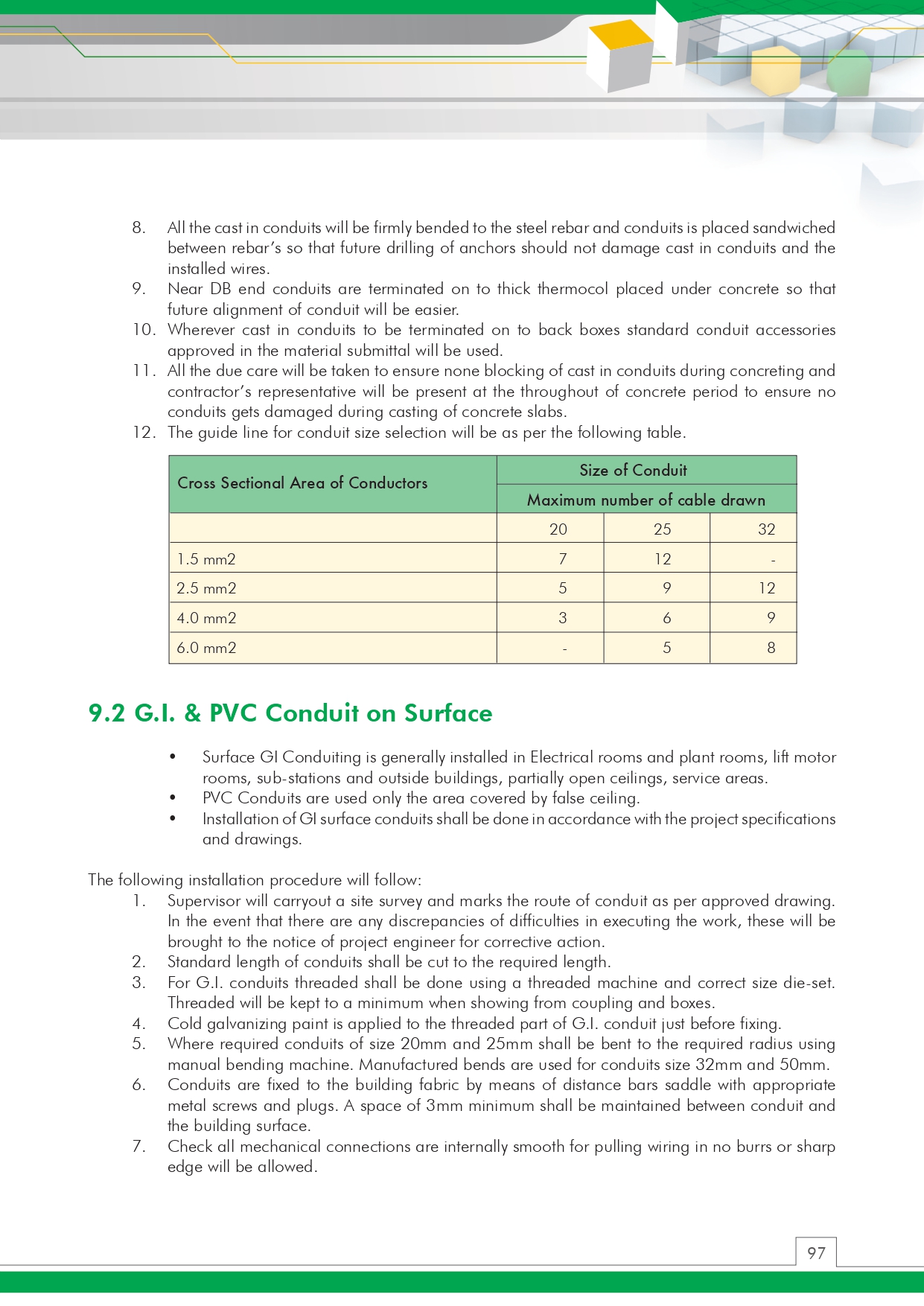
Approved materials, pre-installation inspection, and coordination with consultants.

🚚 7.2 Material Transport & Delivery

Safe transport practices to avoid breakage or damage.

🏗️ 7.3 On-Site Storage

Proper storage conditions to avoid rust, exposure, or deformation.

🔩 7.4 Installation Sequence – From Safety to Final Fix

⚠️ 7.4.1 Safety Measures Before Installation

Toolbox talks, PPE usage, safety checks for chemicals, and trained workers.

📝 7.4.2 Pre-Installation Checklist

Civil clearance, approved materials, proper wall openings, and leak-tested pipes.

🛁 7.4.3 Installation Guidelines for Fixtures & Sanitary Wares

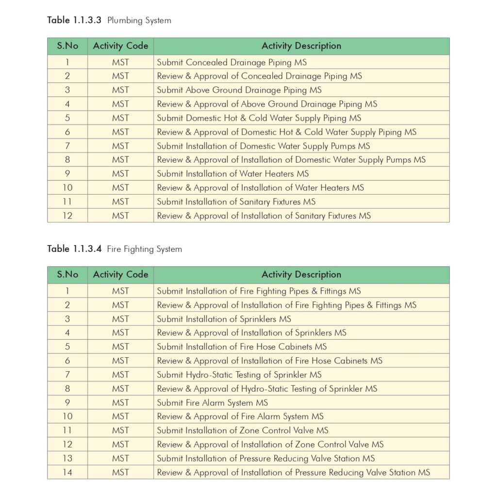
7.4.3.1 Plumbing Fixtures

  • Wall-hung and countertop installation
  • Flow control fittings
  • Stop valve and ball valve integration
  • Protective post-installation covering

7.4.3.2 Sanitary Wares & Accessories

  • Anchoring as per specifications
  • Anti-vandal and rust-resistant installation
  • Electrolysis isolation and protection
  • Final adjustments and safety checks

💧 8.0 Testing & Commissioning – Ensuring Leak-Free, Efficient Operation

🧪 8.1 Pre-Commissioning Checklist

Ensure approvals, water pressure availability, and PRV settings.

🔎 8.2 Flow Rate & Performance Testing

  • Stopwatch testing of flow rates
  • Flush tank operation check
  • Automatic tap sensor response
  • Adjustment for non-compliant flow rates

📎 9.0 Attachments – Supporting Documents for Quality Assurance

Risk Assessment

Quality Control Procedure (QCP)

Inspection & Test Plan (ITP)

Installation Check Sheets

Method Statement for Installation Clean Agent system.

1.0 PURPOSE

The purpose of this method statement is to outline the method for handling, storage, installation, testing and commissioning for the Clean Agent System in accordance with the requirements specified in the relevant NFPA Codes, Standards and Project specifications in all applicable areas for the project.

2.0 SCOPE  

The procedure applies for the installation, testing and commissioning of 200 Bar Clean Agent INERGEN gas fire extinguishing system in at the project.

3.0  REFERENCES

  • Latest Approved shop drawings for the required and applicable areas for the fire fighting layouts.
  • Specifications
  • Project Quality Plan
  • NFPA 2001: Standard for Clean Agent Fire Extinguishing System
  • NFPA 72: National Fire Alarm Code
  • Civil Defence Approval.

4.0  DEFINITIONS

  • FF Sub-Contractor              : SUBCON
  • PQP                                        : Project Quality Plan
  • PSP                                         : Project Safety Plan
  • QCP                                        : Quality Control Procedure
  • HSE                                        : Health, Safety and Environment
  • MS                                          : Method Statement
  • ITP                                         : Inspection Test Plan
  • QA/QC                                   : Quality Assurance / Quality Control Engineer.
  • WIR                                       : Inspection and Test Request
  • AFC                                        : Approved for Construction.

5.0  RESPONSIBILITIES

Responsibilities for ensuring that the steps in this procedure shall be carried out are specified at relevant steps in the procedure:

  • Project Manager
  • Construction manager
  • QA/QC Engineer
  • Site Engineer
  • HSE officer
  • SK
  • FF Sub-Contractor

5.1 Project Manager

  • The work progress shall be carried out as per planned program and all the equipment’s required to execute the works shall be available and in good condition as per project planned.
  • Specific attention is paid to all safety measures and quality control in coordination with Safety Engineer and QA/QC Engineer and in line with PSP and PQP.

5.2 Construction Manager

Construction Manager is responsible to supervise and control the work on site.

5.3 Site Engineer

  • The check and review the method of statement that will be submitted from FF sub-contractor to the system as per Consultant project specifications and approved shop drawings.
  • Supervise and give any assignment for the FF sub-contractor.
  • Provision of all necessary information and distribution of responsibilities to his Construction team.
  • The constant coordination with the Safety Engineer to ensure that the works are carried out in safe working atmosphere.
  • The constant coordination with the QA/QC Engineer for any works to be carried out and initiate for the Inspection for the finished works.
  • He will ensure the implementation of any request that might be raised by the Consultant.
  • Efficient daily progress shall be obtained for all the equipment and manpower.
  • He will engage in the work and check the same against the daily report received from the Foremen.
  • The passage of all the revised information to the Foremen and ensure that it’s being carried out properly.

5.4 QA/QC Engineer (MEP):

  • The monitoring of executions of works at site and should be as per the approved shop drawings and project specifications.
  • Ensure WIRs and MVRs are being raised for activities in timely manner and inspected by the Consultant.
  • He will follow and carried out all the relevant tests as per project specifications.
  • Obtain the required clearance prior to Consultant’s inspections.
  • Should acquire any necessary civil works clearances and coordination.

5.5 Site Foreman

  • The carrying-out of work and the proper distribution of all the available resources in coordination with the Site Engineer on a daily basis.
  • Daily reports of the works are achieved and coordinated for the future planning with the Site Engineer.
  • Incorporate all the QA/QC and Safety requirements as requested by the concerned Engineer.
  • Meeting with any type of unforeseen incident or requirement and reporting the same to the Site Engineer immediately.

5.6 Safety Officer

  • The implementation of all safety measures in accordance with the HSE plan and that the whole work force is aware of its proper implementation.
  • The implementation of safety measures is adequate to maintain a safe working environment on the work activity.
  • Inspection of all the site activities and training personnel in accident prevention and its proper reporting to the Construction Manager and the Project Manager.
  • The site is maintained in a clean and tidy manner.
  • Ensure only trained persons shall operate the power tools.
  • Ensure all concerned personals shall use PPE and all other items as required.
  • Ensure adequate lighting is provided in the working area at night time.
  • Ensure high risk elevated areas are provided are barricade, tape, safety nets and provided with ladders.
  • Ensure service area/inspection area openings are provided with barricade, tape, and safety nets.
  • Ensure safe access to site work at all times.

5.7 Store Keeper (SK)

  • Responsible for overall Store operations in making sure to store the material delivery to the site and keep it in suitable area that will keep the material in safe from rusty and damage.

5.8 FF Sub Contractor

  • FF sub Contractor (SUBCON) will handle the installation, testing and commissioning for the system in supervision from MEP Contractor.
  • The work progress shall be implemented and monitored in accordance with the planned work program and he will provide reports to his superiors and report to MEP contractor.

– The constant coordination with the QA/QC Engineer and the site Engineer for any works to be carried out and initiate for the Inspection for the finished works.

6.0  EQUIPMENT

6.1 General Tools and Equipments:

  • Clean Agent System and Accessories.
  • Pipe hangers and supports
  • Drilling Machine
  • Grinding Machine
  • Pipe Cutting machine
  • Pipe Threading Machine
  • Nylon straps/ shackles
  • Grooving Machine
  • Measuring Instruments (With Valid Calibration Certificates)
  • Calibrated pressure gauge
  • Calibrated Multi meter & Megger
  • Hand Tools
  • Mobile scaffold/ temporary/ high/ low scaffolding and stepladders
  • Chain blocks
  • Mobile scaffold/ temporary/ high/ low scaffolding and stepladders
  • Air compressor
  • Isolation valves
  • Safety requirements tools such as safety shoes, safety helmet, safety glasses, fluorescent vest, and safety gloves to ensure maximum ability of safe work and dust mask when required.

6.2 MATERIAL USED:

INERT GAS CLEAN AGENT (INERGEN)

Inert gas clean agent (Inergen)

Cylinder

  • 200 Bar, 16.2 m3 INERGEN gas cylinders, meets DOT 3AA3000 equipped with CV-98 INERGEN valve, safety relief valve & shipping cap.

Cylinder assembly

  • The bracketing components are constructed of heavy structural steel painted with a red enamel coating.

Distribution piping

  • ASTM A 53 / A 106, Grade B, schedule 160, galvanized – up to pressure reducer orifice union
  • ASTM A 53 / A 106, Grade B, schedule 80, galvanized – after the pressure reducer orifice union.

Nozzles

  • ¼” up to 3” NPT, UL listed
  • Orifice union/flange assemblies
  • A 3000 psi (206.9 bar) union/flange contains a stainless steel orifice plate which is drilled to the specific size hole required based on the flow calculation.

OTHER ACCESSORIES

6.3 PRESSURE TESTING EQUIPMENTS:

  • Pressure Test Pump (1 No.)
  • Calibrated Pressure Gauges – 2 nos.
  • Calibrated Pressure Relief Valve – 1 no.

6.4 Leakage Testing Tools:

  • Pressure Relief Valve (1 No.)
  • Air Compressor (1 No.) or N2 Cylinders for test (1 Set)
  • Calibrated Pressure Gauges (2 Nos.)
  • Isolation valve – 2 nos.

6.5 INTEGRITY TEST EQUIPMENTS:

  • Canvas Sheet
  • Air Current Fan unit
  • Set of tools
  • Sampling tubes c/w fittings (set)
  • 15 meter – Extension Reel
  • Digital Manometer Battery
  • Digital Manometer 200/2000 Pa
  • Digital Thermometer
  • Measuring Tape
  • Tile Lifter
  • Hacksaw Blade

6.6 Pre- Commissioning Tools:

  • Smoke Gun
  • Multi Meter
  • Hand tools

7.0  PROCEDURE

7.1 Safety

  • Ensure only trained persons shall operate the power tools.
  • Ensure all concerned personnel shall use PPE (Personal Protective Equipment) and all other items as required.
  • During the process of testing and commissioning, display warning sign boards necessarily provided and barricade the area, if required.
  • Check whether required guards are provided for rotating equipment’s before first start up.
  • Isolate electrical power supply and lock the switchgear, whether work is to be carried out on any rotating equipment or electrical panels.
  • Ensure adequate lighting is provided in the working area at night time.
  • Ensure service area/work area openings are provided with barricade, tape, and safety nets.

7.2 Work Sequence And Methodology

  • Check all material delivered to site is inspected properly by QA/QC Engineer and check if it is stored properly as per manufacturer’s recommendations.
  • MVR shall be raised for the inspection of materials received at site to the CONSULTANT Engineer.
  • Work shall be carried out by the site staff under strict supervision and guidance of the concerned Supervisors / Foremen / Engineers.
  • The MEP QA/QC Engineer shall check all the installations as per the Installation Check list.
  • WIR shall be prepared by MEP QA/QC Engineer and will be submitted to CONSULTANT for their inspection and approval.
  • MEP QA/QC Engineer shall coordinate with other Contractors and arrange inspection for installation to the CONSULTANT Engineer.
  • MEP QA/QC Engineer is responsible for all installation activities for getting the work inspected / approved by CONSULTANT Engineer.

7.3 Storage

On receipt of 200 Bar INERGEN gas fire extinguishing system materials to site, precautions shall be taken for unloading, handling and storage, as follow: –

  • Before shifting the cylinder storage area to be inspected by safety officer.
  • All materials while unloading shall not be dropped, but lowered slowly to the ground in a smooth manner.
  • Only experienced and properly trained persons should handle compressed gases.
  • Do not remove or deface labels provided by the manufacturer for the identification of the INERGEN cylinder contents.
  • Store the INERGEN gas cylinders with the transportation cap fitted.
  • Store the INERGEN gas cylinders in a location that is free from any potential risk and away from sources of heat and ignition.
  • INERGEN gas cylinders should be stored always in the vertical position and properly secured to prevent toppling.
  • INERGEN gas cylinders kept in the storage area shall be periodically checked for general condition of the cylinder any possible leakage.
  • INERGEN system pipes shall be stacked on a flat surface with adequate supports.
  • Cable reels shall not be rolled or stored without any appropriate underlay.
  • All other items such as INERGEN system valves, flexible connections, etc. shall be kept in racks within the site stores.
  • Any item that is found to be damaged or not suitable shall be replaced with the new item. The removed item, if required to be stored temporarily. They shall be clearly marked and stored separately to prevent any inadvertent use.
  • All cylinders while unloading and shifting in storage area, safety officer to be involved.

7.4 PREPARATION WORK

Before commencing the installation work of the INERGEN system, the following activities shall be ensured:

  • Ensure approved materials are available for the installation.
  • All materials shall be inspected for damages upon receipt of materials in the store.
  • Ensure the “Issued For Construction (IFC)” drawings are available for the installation.
  • Ensure the necessary work permit, if any required is obtained prior to commencement of the work.
  • Ensure the work area is clean and safe for work.
  • Ensure the installation works are under taken only by trained and experienced personnel.

7.5 INSTALLATION ACTIVITIES

7.5.1 INSTALLATION OF MANIFOLDS, PIPES WORK & CYLINDER BANK

  • Install manifolds and system components as per the layout drawings.
  • Manifolds will be fabricated in off site – SUBCON workshop.
  • Install INERGEN cylinder frame & supports as per the drawing and ensure that they are firmly fixed.  The support system shall be recommended by the cylinder suppliers and as per drawings.
  • Position and fix the INERGEN cylinders as per drawings and secure them in the brackets. Before installing cylinders, agent level to be checked.
  • Install manifold pipe works and accessories as per AFC drawings. Check for correct leveling, positioning and alignment of the pipe routing.
  • Connect Cylinder Hose with Inergen Cylinder
  • Install electrical works- cables, junction boxes and actuators as per the P & ID.
  • Termination of Cables for the Solenoid Valve & Pressure Switch to the enclosure with in the Cylinder Room.
  • Pressure relief dampers shall be multi parallel blade with weighted arm closing assist. The frame shall be anodized Aluminium channel sections with formed Aluminium blades. Maximum blade length shall be 100 mm, and polyester foam seating strips shall be incorporated on blade edges. Bearings shall be in PVC with non corrodible shafts as per specs.
  • Install Inergen cylinders as per AFC drawings and secure them in the brackets.
  • Assembly of Distribution Pipes  with in the cylinder Room with Manifold
  • Touch up paint on all paint damaged areas before transporting the container to site.
  • Check the distribution pipes are clean inside and outside and ensure they are free from oil/grease and dust particles.
  • Determine the location of the pipe supports and pipe routes in the trench/building wall/roof.
  • Determine all the pipe sleeves location & mark up in preparation for wall/slab coring.
  • Perform the wall/slab coring using the appropriate drilling apparatus on the marked pipe sleeve location.
  • Mark up anchor bolt positions for pipe supports on the concrete / purlins and drill to required lengths using portable electric drilling machine.
  • Fix supports in position and ensure the supports are fixed securely.
  • Use appropriate lifting equipment to lift the pipes when required.
  • Assemble the pipe works using screwed fittings. Ensure appropriate sealing compound is used for screwed fittings.
  • Clamp the pipe works to supports using U bolts and ensure they are tightly secured.
  • The pipe works shall then be checked for correct leveling, position and alignment.
  • Install temporary caps to any open end of pipes before leaving the work place everyday.
  • Install the pre-assembled cylinder container on the foundation provided.
  • Tie-In of the Cylinder Bank piping and distribution pipe work. Ensure that there is no stress on the pipes.
  • Pipes and fittings to be tighten properly. Any excess cut / damage during tightening of pipes and fitting, then the same shall be replaced.

7.5.2 INSTALLATION OF CABLE WORKS

  • Cables shall be pulled manually and clipped through the wall & ceiling’s surface from the drum end to the termination end.
  • Ensure sufficient length is maintained to connect to the devices as per the approved drawings before cutting the cable.
  • The minimum bend radius will be as per manufacturer’s specifications.
  • Cable identification and tagging shall be in accordance with the approved drawings and project specification.
  • Perform cable insulation test and ensure continuity of all cable cores. The results of all the tests to be recorded on approved forms.
  • All test equipments used on site shall be accompanied by a current set of calibration certificates.
  • Earthling of devices/panels shall be in accordance with the project specifications.
  • Use only approved seals on walls and flooring penetrations.
  • Correct conductor polarity shall be maintained during connection to devices.
  • Identification at the Fire Alarm panel and all associated connector blocks shall be in accordance with standard industrial practices.
  • Prepare as-built drawings where necessary for relevant information to allow CAD department to amend existing drawings.

7.5.3 INSTALLATION OF FIRE ALARM FIELD DEVICES & LOCAL FIRE ALARM PANEL FOR EXTINGUISHING CONTROL

  • Install Manual Call Points, Sounders/Beacons and accessories as per the approved construction drawings and manufacturer’s instructions and check the soundness of installation and alignment of the devices.
  •  All abort Switched, manual release devices shall be installed as per approved shop drawings.
  • Terminate the cabling to the devices.
  • Label the devices as per the tag numbers given in the drawing.
  • Check the Local fire alarm panel for extinguishing control and its internal components including batteries before installation for any damage.
  • Install the Local fire alarm panel for extinguishing control as per the approved construction drawings and manufacturer’s instructions.
  • Earthings of the panel shall be connected to the electrical Earth bar.
  • Upon completion of cable pulling coming from the field devices, termination of cables shall be done.
  • Power supply and battery connection shall be terminated after all system devices are in place.
  • Clean the inside part of the panel upon completion of all cable termination and lock the door.
  • Label the control panel as per the tag numbers given in the approved drawing.

7.6 FLUSHING & LEAK TESTING OF THE PIPING

  • By blowing air, flush the complete piping prior to leak testing. Refer to the Testing sheet.

7.6.1 Leakage Test Procedure:

7.6.1.A TEST REQUIREMENTS

Before commencement of any leak testing for piping, ensure that the following are met:

  • Ensure that pipe supports and brackets are firmly secured the installed pipe work in position.
  • Ensure that the piping has been flushed by clean air blowing and verified.
  • Test area properly barricaded and signs posted to keep out of all non-essential personnel.
  • All in-line instruments (cylinders, pressure switches & vent plugs) are isolated from the test by means of blanking off plugs or caps.

7.6.1.B TEST PROCEDURE

  • The pneumatic leak test using air medium shall be conducted with all the temporary openings sealed by plugs / end caps – with no system components installed (like, gas discharge nozzles).

.

  • An air compressor shall be connected to the pipe work at one of the manifolds ensuring that after pressurization of the pipe line being tested, the unit can be disconnected with the pipes pressurized (from the cylinders line – via check valve – to manifold / pipes end).
  • 2 Nos. of calibrated pressure gauges, each having a range from 0 – 20 bar shall be used for testing. One pressure gauge shall be fitted at the start point and the second pressure gauge at the high level point at the farthest end.
  • The testing shall be done at ambient temperature range.
  • The system shall be gradually pressurized in steps of 5 PSI to reach 40 PSI (2.76 bar). A five minute interval shall be provided after each step to allow the air pressure to stabilize.
  • After reporting required test pressure, check for leaks with a soap solution at each joint. If any leak is found, depressurize the system, repair the leak(s) and re-test.
  • The test pressure of 40 PSI (2.756 bar) shall be maintained for 10 minutes minimum. The pressure drop shall not exceed 20% of the test pressure at the end of 10 minutes. If the pressure drops more than 20%, the testing shall be discontinued and leaking joint(s) shall be identified / repaired and a new test conducted.
  • On satisfactory completion of the pneumatic test, the pressure shall be gradually reduced and system depressurized.
  • The test certificate shall be completed with necessary signatures obtained.

7.7 INSTALLATION OF THE DISCHARGE NOZZLES

  • Install the discharge nozzles in accordance with the layout drawing. Ensure correct nozzle sizes are fitted at specified locations as per the layout drawing / as – built gas flow calculations.

7.8  “Puff” Testing of the Piping

  • Blow air through the piping to make certain that all discharge nozzles are free from any blockages and to confirm that all check valves (if applicable) operate correctly.

7.9 FINAL PAINTING AND IDENTIFICATION

Final Painting

  • Paint touch-up of the system pipe works/supports shall be carried out at places, where paint damages have occurred using approved paint system.

Signage

  • Identification labels, operating instructions and warning signs in English and

       Arabic shall be provided as appropriate.

      7.10 Pressure Testing:

  • The manifolds shall be pressure tested one and half time of the design pressure of the 200 Bar INERGEN gas fire extinguishing system. All the manifolds shall be looped together and hydro tested at 300 Bars for a period of 2 Hours.

7.10.1 Test Preparation:

 Before commencement of pressure testing of the manifold, the following shall be ensured:

  • All used materials have approved material certificates.
  • The manifolds have been fabricated as per approved drawings.
  • All manifolds to be tested shall be temporarily connected together by coupling and piping made for the testing.
  • The pressure test should be conducted with no system components installed in the line.

7.10.2 Test Procedure:

  • Connect two calibrated pressure gauges to the system pipe work to be tested. One gauge shall install near the test pump and the other at the farthest end.
  • A calibrated pressure relief valve set at a cracking pressure of 330 bars shall be installed in the line.
  • A test pump shall be connected to the piping ensuring that the pump can be disconnected from the manifold when the pipes are pressurized.
  • The manifold piping shall then be slowly filled with clean potable water using the pump. During water filling, the test crew must ensure that the system is completely vented.
  • The piping system shall be slowly pressurized giving 5 minute interval in between every 100 bar. Pressure increase until a pressure of 300 bars is attained.
  • A visual inspection shall be made on every joint for leakage. If any leaks are found, the system shall be drained and necessary repairs shall be done.
  • When it is evident that there are no leaks or drop in the indicated pressure, the pressure shall be maintained for a period of 2 hours at ambient temperature.
  • Record the readings indicated in the pressure gauge after every 60 minutes.
  • On satisfactory completion of the test, the water in the manifold piping shall be drained off and the pipes shall be dried up by blowing air.
  • Fill in and complete the test certificate and obtain the necessary signatures.
  • The test certificate shall be completed with necessary signatures obtained.

7.11 INTEGRITY TEST:

 7.11.1 PRETEST PROCEDURE

7.11.2  PREPARATIONS

  •  
  • Ensure that the necessary work permit (if required) is obtained.
  • Barricade the area.
  • Inspect the room thoroughly for any openings not sealed, windows / doors opened.
  • Ensure that the HVAC system is switched off and all the inlet / outlet dampers are closed.

NOTE:

The air-conditioning / ventilation system must be closed during the test. The required isolation duration will be around 2 hours for each protected area.

7.11.3 TEST PROCEDURE

  • The procedure involves the fitting of a variable speed fan unit into an existing doorway by means of an adjustable door frame. The fan is used to pressurize and de-pressurize the enclosure with a known / measured quantity of air of very low pressure.
  • Leakage is quantified by measuring the air flow rate and the developed pressure within the enclosure. A computer is used to calculate the “effective leakage area” (ELA) which is the sum total of all leakage sites within the perimeter of the enclosure.
  • The test is essentially a two part test.
  • The first part of the test uses a fan that quantifies the leakage areas within the enclosure and provides a calculation of the effective leakage area (ELA).
  • The second part of the test involves the use of a computer model to predict whether the INERGEN gas would be held for a specified period.
  • Personnel can be inside the enclosure during tests however, they must remain inside until tests are completed.

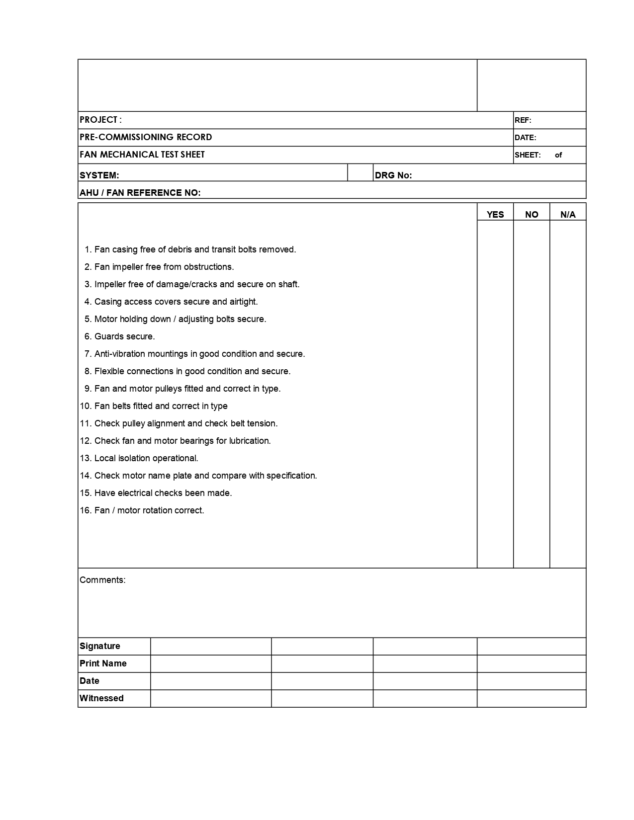
7.11.4 Part 1: FAN TEST

  • Ensure all pre-works were completed.
  • Complete the fit-out of adjustable door frame and fan unit in door way. Connect the manometer and the pressure sampling tubes.
  • After the equipment set-up, finalize preparations for the actual test.
  • Fix the sign stating “DO NOT ENTER / CLOSE DOOR – FAN TEST IN PROGRESS”. The sign shall be posted in English.
  • Fill the integrity test record form except the readings to be taken during the test.
  • Take the readings of static pressure within the enclosure as appropriate.
  • Perform Depressurization Test – the fan to be switched on and by varying the quantities of air blown into the protected enclosure, it will create negative pressures within the enclosure.
  • Perform Pressurization Test – the fan to be switched on and by varying the quantities of air blown out of the protected enclosure to create Positive pressures within the enclosure.

7.11.5 Part 2: COMPUTER CALCULATION

  • Following the completion of the Pressurization and Depressurization tests, the readings taken are entered into the computer along with the details of the INERGEN gas fire extinguishing system and calculation of the effective leakage area (ELA) are made as well as the prediction of the INERGEN gas retention time on the basis of design parameters.
  • In case the enclosure does not hold 10 minutes retention time, then the client may need to obtain services of Specialist Consultant to seal the protected enclosure.
  • After completion of the above, the room can be turned back to its normal stage.

7.11.6 INTEGRITY TEST REPORT

Upon completion of the tests, a full report shall be prepared and test results shall be compiled by the Engineer.

7.12 Final Pre-Commissioning & Commissioning:

7.12.1 METHODOLOGY

Before commissioning the 200 Bar INERGEN gas fire extinguishing system the following pre-commissioning checks shall be ensured: –

7.12.1-A PRE-COMMISSIONING

  • Ensure that the installation activity of the INERGEN gas fire extinguishing system is completed.
  • Ensure that the INERGEN system has been checked against the approved installation drawings.
  • Ensure that the pipes are cleaned by blowing air.
  • Ensure that the leak test of the piping has been carried out and witnessed.
  • Ensure that the discharge nozzles and orifice units have been installed in accordance with the approved gas flow calculations.
  • Ensure that the actuation hose and discharge hose are rigidly fitted.
  • Ensure that the 200 Bar INERGEN gas cylinder pressure gauges showing the acceptable pressure range.
  • Ensure that the installation of control panel and associated cabling / installation of devices are completed and tested.
  • Ensure that the termination to all devices (like smoke detectors, bells, flasher beacons, solenoids & pressure switches) are completed and loops are checked.
  • Ensure that all the identification and warning signs, flow directions are marked as appropriate / required.
  • Ensure that the solenoid actuator is disconnected from the master cylinder.
  • Ensure that the room integrity testing of the protected room is completed to ensure that the openings inside the room are within the acceptable limit and the results are acceptable.
  • All results will be recorded in the attached Sheet.

 7.12.1-B COMMISSIONING

  • Before commencing the commissioning activities, please ensure that solenoid actuator is disconnected from the master cylinder and all loops have been checked for continuity and are witnessed by client / contractors.
  • Switch ON the power for the control panel and check for the following functions of the control panel
  • Using Auto / manual / disabled key switch, check the operation of system status indication  

Operate 1 NO. of smoke detector in the protected area using a smoke gun and confirm the FOLLOWING Sequence of operations:

  • Common fire alarm bell & common fire beacon in the building activate.
  • Fire indication on the Extinguishing Control Panel operates.
  • Fire signal on the F&G Panel and the shutdown of equipments.

Operate one more detector in the protected area and confirm the FOLLOWING SEQUENCE OF OPERATIONS:

  • Pre-discharge sounder inside & outside the protected room is active. (intermittent Tone)
  • On expiry of time delay period, confirm that the INERGEN solenoid actuator is activated.
  • Discharged sounder/beacon outside protected area is activated. (Tone continuous)

Operate the gas discharge pressure switch and confirm the following:

  • Gas discharge message on the Extinguishing Control Panel is activated.
  • Gas discharge message on the F&G  panel is activated
  • Indication on Extinguishing Control Panel (INERGEN gas discharge completed) is activated

 Placing the system in service:

  • On completion of the tests as per above, reset the panel and install the solenoid on the master cylinder to place the system in service
  • Install the manual release leaver to the master cylinder.

8.0 ATTACHMENTS

  • 8.1 Inspection & Test Plan
  • 8.2 Check Lists                                                          
  • 8.3 Risk Assessment              
Fire

🚒 Fire Fighting Piping System Installation & Testing Method Statement

1.0 🔍 Purpose

This method statement outlines the step-by-step process for the installation, testing, and commissioning of the Fire Fighting Piping System and all related accessories across the project site.


2.0 📌 Scope of Work

This document covers the:

  • Supply of fire fighting piping and fittings
  • On-site installation of piping networks and accessories
  • Testing and commissioning of the complete fire protection system
  • Compliance with project requirements and local authority standards

3.0 📁 References

3.1 Drawings:

  • All approved Fire Fighting Layouts

3.2 Specifications:

  • Local authority guidelines
  • Civil Defense requirements
  • Project-specific specifications

4.0 📘 Definitions

  • Main Contractor: Overall project controller
  • Subcontractor: Assigned fire fighting works contractor
  • Quality Engineer: Site-based QA/QC representative
  • Project Engineer: Designated engineering lead
  • AWS, ASME, ASTM, AWWA, FDC, FM, NFPA, NPSH, UL: Industry-standard abbreviations

5.0 👷‍♂️ Responsibilities

  • Project Manager: Ensures project compliance and execution
  • Construction Manager: Oversees daily site operations
  • Site Supervisor/Foreman: Maintains manpower productivity and workmanship
  • QA/QC Engineer: Verifies compliance with drawings and specifications

6.0 🛠 Tools & Equipment

Ensure availability of the following tools before work starts:

  • Manual testing pump
  • Threading and grooving machines
  • Pipe wrench, cutter, and saw
  • Welding machine
  • Measuring tape, marker, and chalk line
  • Adjustable and fix spanners
  • Electric drill and bits
  • Fire extinguisher
  • Scaffolding and lifting gear

7.0 📋 Installation & Testing Procedure

7.1 General Requirements

  • Use only approved materials and shop drawings
  • Conduct material inspection with MIR
  • Verify approval from consultant and Civil Defense

7.2 Material Handling

  • Store pipes with end caps on level, dry surfaces
  • Use timber supports every 1.5m to avoid deformation

7.3 Pipe Installation

🔽 Below Grade

  • HDPE pipes to be installed in pre-approved trenches
  • Use soft sand bedding and concrete encasement where necessary
  • Electro-fusion welding for HDPE jointing
  • Warning tapes to be installed per drawings

🔼 Above Grade

  • Avoid routing above electrical systems
  • Mark and install supports per NFPA 13
  • Use GI sleeves and fire sealing for pipe penetrations
  • Jointing to follow ASME/AWWA standards:
    • Flanged, threaded, grooved, or twist-lock types
    • Use stainless steel fasteners for outdoor use
    • Apply corrosion-resistant paint (Post Office Red)

7.4 🔧 Accessories Installation

  • Install air vents, drain points, and inspector’s test connections
  • FDCs to include automatic drain valves
  • Trim and gauges to be properly routed and supported

7.5 💦 Valve Installation

  • Install valves as per NFPA 13 and authority requirements
  • Integrate zone control valves with FAS and BMS
  • Provide OS&Y valves with tamper switches

7.6 Specialty Valves

  • Alarm valves to include retarding chamber and bypass check valves
  • Ensure vertical installation with correct flow direction

7.7 ✅ System Identification

  • Label all piping and system components
  • Follow NFPA 13 and project specification labeling standards

7.8 🔍 Hydrostatic Testing

  • Pressure test system at 1.5x working pressure for 2 hours
  • Use only calibrated gauges
  • Flush the system with potable water until clean
  • Record and file all test results

8.0 📎 Attachments

  • ✔ Quality Control Procedures
  • ✔ Inspection & Test Plan (ITP)
  • ✔ Pre-commissioning Checklists
  • ✔ Pipe Pressure Test Certificates
  • ✔ Risk Assessment Reports

Method of Statement for Installation, T&C of External Fire Hydrant.

1.0 PURPOSE

This method statement is applicable for the Installation, Testing & Commissioning of External Fire Hydrant for the project as mentioned in the Specifications & Approved Shop Drawings.

2.0 SCOPE

This method Statement shall cover the Supply, Installation, Testing & Commissioning of External Fire Hydrant in line with project requirements as indicated in the Approved Shop Drawings, specifications & manufacturer’s instructions.

3.0 REFERENCES

  • Latest Approved shop drawings intended for Fire Fighting System
  • Specifications
  • Project Quality Plan
  • Project HSE Plan
  • Material Approval
  • Approved Method Statement for Installation & Testing for Fire Fighting System & Accessories

4.0 DEFINITIONS

  • PQP                             : Project Quality Plan
  • PSP                              : Project Safety Plan
  • QCP                             : Quality Control Procedure
  • HSE                             : Health, Safety and Environment
  • MS                               : Method Statement
  • ITP                               : Inspection Test Plan
  • QA/QC                        : Quality Assurance / Quality Control Engineer.
  • WIR                             : Inspection and Test Request
  • MIR                             : Material Inspection Request
  • UPVC Class E              : Ultra polyvinyl chloride
  • UPVC                          : Ultra polyvinyl chloride
  • HDPE                          : High density polyethylene
  • PEX PIPE                     : Cross-linked Polyethylene
  • G.I. Pipe                       : Galvanized Iron Pipe

5.0 RESPONSIBILITIES

  • Responsibilities for ensuring that the steps in this procedure shall be carried out are specified at relevant steps in the procedure:
  • Project Manager
  • Construction manager
  • QA/QC Engineer
  • Site Engineer
  • HSE officer
  • SK

5.1 Project Manager

The work progress shall be carried out as per planned program and all the equipment’s required to execute the works shall be available and in good condition as per project planned.

Specific attention is paid to all safety measures and quality control in coordination with Safety Engineer and QA/QC Engineer and in line with PSP and PQP.

5.2 Construction Manager

Construction Manager is responsible to supervise and control the work on site.

5.3 Site Engineer

The method of statement to the system shall be implemented according to the Consultant project specifications and approved shop drawings.

Provision of all necessary information and distribution of responsibilities to his Construction team.

The work progress shall be monitored in accordance with the planned work program and he will provide reports to his superiors.

The constant coordination with the Safety Engineer to ensure that the works are carried out in safe working atmosphere.

The constant coordination with the QA/QC Engineer for any works to be carried out and initiate for the Inspection for the finished works.

He will ensure the implementation of any request that might be raised by the Consultant.

Efficient daily progress shall be obtained for all the equipment and manpower.

He will engage in the work and check the same against the daily report received from the Foremen.

The passage of all the revised information to the Foremen and ensure that it’s being carried out properly.

5.4 QA/QC Engineer (MEP):

The monitoring of executions of works at site and should be as per the approved shop drawings and project specifications.

Ensure WIRs and MIRs are being raised for activities in timely manner and inspected by the Consultant.

He will follow and carried out all the relevant tests as per project specifications.

Obtain the required clearance prior to Consultant’s inspections.

Should acquire any necessary civil works clearances and coordination.

5.5 Site Foreman.

The carrying-out of work and the proper distribution of all the available resources in coordination with the Site Engineer on a daily basis.

Daily reports of the works are achieved and coordinated for the future planning with the Site Engineer.

Incorporate all the QA/QC and Safety requirements as requested by the concerned Engineer.

Meeting with any type of unforeseen incident or requirement and reporting the same to the Site Engineer immediately.

5.6 Safety Officer.

The implementation of all safety measures in accordance with the HSE plan and that the whole work force is aware of its proper implementation.

The implementation of safety measures is adequate to maintain a safe working environment on the work activity.

Inspection of all the site activities and training personnel in accident prevention and its proper reporting to the Construction Manager and the Project Manager.

The site is maintained in a clean and tidy manner.

Ensure only trained persons shall operate the power tools.

Ensure all concerned personals shall use PPE and all other items as required.

Ensure adequate lighting is provided in the working area at night time.

Ensure high risk elevated areas are provided are barricade, tape, safety nets and provided with ladders.

Ensure service area/inspection area openings are provided with barricade, tape, and safety nets.

Ensure safe access to site work at all times.

5.7 Store Keeper (SK)

Responsible for overall Store operations in making sure to store the material delivery to the site and keep it in suitable area that will keep the material in safe from rusty and damage.

6.0 EQUIPMENTS

Following tools shall be arranged before starting the job.

  1. Tool Box.
  2. Measuring Tape.
  3. Hack Saw Blade
  4. Spirit Level
  5. Electric Drill Machine
  6. Step Ladders
  7. Threading Machine
  8. Solvent Cement
  9. Electric welding machine. (if required)
  10. Torque Wrench
  11. Pipe Cutting Machine
  12. Grinding Machine
  13. Pressure Gauge
  14. Hammer
  15. Water Level Marker
  16. Mobile Scaffolds
  17. Staging Platforms

7.0 PROCEDURE

Work Sequence/Procedure

  7.1 General Requirements

  • All the materials received at site shall be as per the approved technical material submittal for  External Fire Hydrant to be inspected upon receipt & approved by the engineer prior in proceeding with the installation through MIR. Any discrepancies, damages etc., should be reported to the supplier for rectification or replacement & to be removed from site immediately.
  • All construction/inspection/testing works shall be carried out in accordance with the specifications & to be done by qualified Mechanical Engineers and shall be checked and approved by MEP Subcontractor Construction Manager along with QA/QC Engineer.
  • Contractor has to clarify the procedure for material delivery to the site through Consultant Engineer at site.

7.2 Delivery & Storage

7.2.1 Material Transport/ Delivery

  • During transportation ensure that the equipment & its components (if any) are delivered in a shipping package and or shall be at least in a box covered with plastic. Extra care in unloading the equipment is required to avoid scratching or denting.
  • Where ever possible the loading and offloading of the External Fire Hydrant shall be carried out by hand. If weight cannot bear by hand, fork lift shall be used.
  • Equipment shall not be dropped onto hard surfaces & should not be dragged along the ground.
  • All the received units shall be checked & inspected to ensure that it is complying with the approved material submittals prior to site storage.

7.3        Storage

7.3.1    Storage on Site Store

  • To ensure that deterioration of the External Fire Hydrant does not occur during storage, it is recommended to store the equipment in sheltered conditions that are protected from weather elements and accidental damage.
  • External Fire Hydrant shall be protected with plastic/ tarpaulin or shall not be removed from the shipping package unless otherwise instructed to do so.
  • All packages for the equipment reaching the site shall be identified as per package list.

7.4 Sequence of Installation for the External Fire Hydrant

7.4.1 Safety

  • All site safety rules & regulations shall be complied with.
  • Supervisors will deliver tool box talks, relevant to these activities to all operatives involved in the installation, testing & commissioning and shall be recorded.
  • All operatives will be equipped with minimum personnel protective equipment; hard hat, coveralls, safety boots, safety glasses.
  • The persons using cleaning fluid and solvent cement have to wear hand gloves.
  • Ensure only qualified personnel shall install, test & commissioned the equipment.
  • During Testing & Commissioning, display warning sign boards necessarily provided and barricade the area whenever necessary.
  • Ensure that all operatives fully understand the method of these activities.

7.4.2 Pre- Installation Procedure

Before commencement of installation activity, the supervisor must ensure that:

  • Delivered Fire Hydrants shall have been inspected & approved via MIR by the Consultant prior to installation at site.
  • All Installations & Pressure Testing of Fire Fighting Pipe works have been completed & approved by the Consultant.
  • Relevant documents or certificates shall be presented at the time of inspection if required by the Consultant.
  • Permission to start or Civil Clearances prior to installation has been given by the main contractor.
  • All relevant Shop drawings for the installation of the equipment shall be available & approved by the Consultant. No installation shall be done without Approved Shop Drawings.
  • Installation activities shall only commence when all associated works by the Civil have been verified & completed.
  • Safe access shall be provided by the Main Contractor thru Work Permit in coordination with the Safety in charge at site.
  • Inspect the relevant area for any possible clashes with other services.
  • Check for other services, making sure that there is no interference between each service & adequate access to work and for future maintenance can be maintained.

7.4.3 Installation Procedure for the External Fire Hydrant

  • Prior to installation, ensure that all External Fire Hydrants are equipped with associated appurtenances as per manufacturer standard & supply according to the approved material submittal.
  • All External Fire Hydrants shall be covered & protected for moisture, corrosion, dust & any deterioration before & after the installation.
  • Ensure all pipework to be connected to the External Fire Hydrant has the proper size & have been hydraulically tested.
  • Pipes shall be free of debris or dirt prior to connection.
  • Mark the location & size of the Valve pit in preparation. Inform civil staffs for construction.
  • Valve pits shall be of concrete construction to adequately house the valves.
  • Ensure that the location of the valves are readily accessible for inspection, operation, testing & for future maintenance.
  • Provide plinths for the External Fire Hydrants. Size of plinths shall be as per the size requirement & size shall be as per the approved details.
  • Place the External Fire Hydrant on the plinths as per the approved installation details.
  • Each fire hydrant will be provided with isolation valve with the correct size.
  • Ensure that the isolation valve shall open & close from the surface of the ground level.
  • Whenever required, provide valve pit covers on the pit for protection.
  • After installation, raise an inspection to the Consultant for approval & acceptance.

7.4.3.2.2 Installation Procedure of Butterfly Valves:

  • Install butterfly valves as per the approved drawings. Ensure that it is readily accessible for operation & maintenance.
  • Ensure valve disc does not interface with the operation of other system components adjacent to the butterfly valve.
  • If the valve is hard to close, it may be due to debris lodge in the sealing area. This can be corrected by backing-off the hand wheel and closing it again several times if necessary. Don’t force the valve to seat by applying a wrench to hand wheel. This may distort the valve components or scratch the sealing surfaces.
  • The inlet & outlet piping of the valve shall be properly supported to prevent excessive stress to the valve body. Do not use the valve body to support pipeline position as it may result in distortion of the valve body.

7.4.4. Testing & Commissioning Procedures

7.4.4.1 Visual Inspection & Testing Procedure

  • After documentations & visual checks, Testing shall proceed further.
  • Ensure all pipe works has been hydrostatically tested & completed. Refer to Approved Method Statement Ref. No.: MS-6012-0021 Rev.02.
  • All supporting system has been completed, properly installed & fixed.
  • Ensure all instruments (if required) to be used during the testing shall be calibrated & records shall be available.
  • Ensure that the all Equipment is in their proper location as mentioned on the Approved Shop Drawings.

7.4.4.2 Commissioning Procedure for the External Fire Hydrant

  • Prior to commissioning, ensure that all instruments (if any) to be used during the commissioning shall be calibrated. Calibration certificates shall be available.
  • Ensure that all installed External Fire Hydrants & Valves have been installed as per the approved shop drawings, manufacturers’ recommendation.
  • Piping system has been tested for leaks. Approval for all preliminary inspections shall be available during the commissioning stage.
  • Ensure all External Fire Hydrants have been installed & fix properly with the correct alignment & spacing.
  • Ensure firmness & tightness of supports prior to Commissioning of the Fire Hydrant.
  • Verify that the external Fire Hydrant shall be easily accessible.
  • Verify that the hydrant has been fitted with maintenance record tag.
  • Verify that signage has been provided that clearly indicates the location of the fire hydrant.
  • Simulate fire conditions by opening a valve.
  • Verify that all water flow alarm & valve monitoring system switches operate correctly.
  • Verify water pressure & flow at the hydrant.
  • Connect a fire hose & open the fire hydrant valve. The water throw shall be at least 20 meters.

8.0 ATTACHMENTS

  • Inspection & Test Plan                                      
  • Installation Check Sheet                                          
  • Testing & Commissioning Check Sheet                  
  • Risk Assessment         

Method statement for Drainage pipe installation & Testing.

1.0 PURPOSE

This method statement is applicable for Installation & testing of all types drainage piping system in all areas for the project.

2.0 SCOPE

Supply , installation & testing of drainage piping system for all applications in line with project requirements.

3.0 REFRENCE

  • Latest Approved shop drawings for the required and applicable areas for  Drainage.
  • Specification:
  • ISO 9001:2008.
  • Project Quality Plan
  • Material Approval Request references:

4.0 DEFINITIONS.

  • PQP: Project Quality Plan
  • PSP: Project Safety Plan
  • HSE: Health, Safety and Environment
  • MS : Method Statement
  • ITP: Inspection Test Plan
  • QA/QC: Quality Assurance / Quality Control Engineer.
  • WIR: Inspection Request
  • MIR: Material Request
  • PP-R pipe  : Polypropylene random copolymer (PP-R), PN-20 to DIN 8077 and 8078 for sizes up to 4″ diameter for above grade.
  • PEX Pipe : polyethylene cold and hot water pipe installed inside the Toilets DIN16892/93.
  • PE 100 pipes: Polyethylene SDR 11 Domestic cold water pipes for below grade installation.
  • PRV: Pressure Reducing Valve.

5.0 RESPONSIBILITIES:

Responsibilities for ensuring that the steps in this procedure shall be carried out are specified at relevant steps in the procedure:

  • Project Manager
  • Construction manager
  • QA/QC Engineer
  • Site Engineer
  • HSE officer

5.1 Project Manager

The work progress shall be carried out as per planned program and all the equipment’s required to execute the works shall be available and in good condition as per project planned.

Specific attention is paid to all safety measures and quality control in coordination with Safety Engineer and QA/QC Engineer and in line with PSP and PQP.

5.2 Construction Manager

Construction Manager is responsible to supervise and control the work on site.

5.3 Site Engineer

The method of statement to the system shall be implemented according to the Consultant project specifications and approved shop drawings.

Provision of all necessary information and distribution of responsibilities to his Construction team.

The work progress shall be monitored in accordance with the planned work program and he will provide reports to his superiors.

The constant coordination with the Safety Engineer to ensure that the works are carried out in safe working atmosphere.

The constant coordination with the QA/QC Engineer for any works to be carried out and initiate for the Inspection for the finished works.

He will ensure the implementation of any request that might be raised by the Consultant.

Efficient daily progress shall be obtained for all the equipment and manpower.

He will engage in the work and check the same against the daily report received from the Foremen.

The passage of all the revised information to the Foremen and ensure that it’s being carried out properly.

5.4 QA/QC Engineer (MEP):

The monitoring of executions of works at site and should be as per the approved shop drawings and project specifications.

Ensure WIRs and MIRs are being raised for activities in timely manner and inspected by the Consultant.

He will follow and carried out all the relevant tests as per project specifications.

Obtain the required clearance prior to Consultant’s inspections.

Should acquire any necessary civil works clearances and coordination.

5.5 Site Foreman.

The carrying-out of work and the proper distribution of all the available resources in coordination with the Site Engineer on a daily basis.

Daily reports of the works are achieved and coordinated for the future planning with the Site Engineer.

Incorporate all the QA/QC and Safety requirements as requested by the concerned Engineer.

Meeting with any type of unforeseen incident or requirement and reporting the same to the Site Engineer immediately.

5.6 Safety Officer.

The implementation of all safety measures in accordance with the HSE plan and that the whole work force is aware of its proper implementation.

The implementation of safety measures is adequate to maintain a safe working environment on the work activity.

Inspection of all the site activities and training personnel in accident prevention and its proper reporting to the Construction Manager and the Project Manager.

The site is maintained in a clean and tidy manner.

Ensure only trained persons shall operate the power tools.

Ensure all concerned personals shall use PPE and all other items as required.

Ensure adequate lighting is provided in the working area at night time.

Ensure high risk elevated areas are provided are barricade, tape, safety nets and provided with ladders.

Ensure service area/inspection area openings are provided with barricade, tape, and safety nets.

Ensure safe access to site work at all times.

5.7 Store Keeper (SK)

Responsible for overall Store operations in making sure to store the material delivery to the site and keep it in suitable area that will keep the material in safe from rusty and damage.

6.0 EQUIPMENTS

Following tools shall be arranged before starting the job.

  • Tool Box.
  • Measuring Tape.
  • Hack Saw Balde .
  • Spirit Level.
  • Excavator.
  • Thedoiled.
  • Manual pressure Pump.
  • Calibrated pressure gauge .
  • Isolation valves ( Pluge or gate type )
  • Flexible Hose with Clamps.
  • Solvent Cement.
  • Electric welding machine.

7.0   PROCEDURE

Work Sequence/Procedure (Installation & Leak Test Procedure of drainage pipes).

7.1 General Requirements

All the materials received at site shall be as per the approved technical material submittals

& to be inspected upon receipt & approved by the engineer prior proceed with installation through MIR & Any discrepancies, damages etc, should be reported  to the supplier for further action & to be removed from site immediately.

All construction/inspection/testing works shall be carried out in accordance with specifications & to be done by qualified Mechanical engineers and shall further to be checked and approved by MEP Subcontractor construction Manager along with QA/QC Engineer.

Contractor has to clarify the procedure for material delivery to the site through consultant Engineer at site.

7.2        Handling

7.2.1     Handling (for Drainage pipes)

During transportation pipes must be handled with care. Do not drop or drag pipes especially on hard surfaces. This is particularly important where the pipe ends have been pre-prepared in the form of spigots (e.g. chamfered ends) and integral sockets.

Where ever possible the loading and Off loading of pipes to be carried out by hand.When mechanical lifting equipment is to be used, no metallic slings, hooks or chains should used in direct contact with the pipe.  Ropes or web slings are preferred, as they will not damage the pipes.

7.3        Storage

7.3.1    Storage on site (for Drainage pipes)

Drainage Pipes should be stored on a flat dry level surface free from sharp projections, stones or other objects likely to cause point loading or pipe deformation. Timber supports spaced 1.5m apart along the pipe can be used to support the pipes.  The width of the stack should not exceed 3m.

Pipes of different sizes should be stacked separately or where this is not possible, hose with larger diameters and/or thicker walls should be placed at the bottom of the stack. The height of the stack should never exceed 7 layers or maximum 2m high.

All pipes and fittings should be properly covered with tarpaulins to protect them from UV rays.  The tarpaulins are to be fixed to the wooden supports, which allow a free passage of air around the pipes.

Fittings will be stored in sheltered conditions in the boxes as supplied to protect them from weathering and accidental damage.

7.3.2 Transport of the drainage pipes:

The vichele should have flat bed freefrom sharp projections of any kinds. Also the pipes must be supported strongly inside the vichel and should not overhand pipe lengh more than 1 meter.

The larger size and thicker pipes should be loaded first. And for more information you can check the below photo.

7.4 Sequence of installation for Drainage piping:

The drainage piping in this project divided into 3 types:

  • UPVC  ( Solvent Cement/ Push Fit Joint) above ground.
  • UPVC class E  ( Push Fit  Joint ) for External underground.( Between Manhole ).
  • HDPE pipe  ( Electro fusion Welding ) for chemical Waste ( Inside & Outside the building ).

7.4.1 Above Ground Piping (UPVC):

  • After getting the all civil clearances (including Raft Slabs , levels, blinding, water proofing & steel fixing), prepare the pipe length & all accessories as per  the approved shop drawing for the laying where applicable .
  • Proceed with pipe Installation with the appropriate Slope and Route as per the approved Shop Drawing using suspended supporting system as per the project specification & leakage test to be applied to insure no leakage from joints & pipes.
  • Pipes joint shall not place in the passage of pipes through the concrete wall.
  • Check all the joints and pipe slope before closed the false ceiling or shafts.

solvent cement weld Joint:

  • Measure length of pipe required, making due allowance for any pipe fittings to be used. Cut the pipe to the measured length. Ensure that the ends are cut square and clean all burs. A chamfer to the depth of half wall thickness to be applied to each spigot.
  • The spigot and socket to be jointed should be carefully examined for any damage which could impair the jointing procedure.
  • The spigot insertion depth should be measured as the depth from the mouth to the shoulder of the socket.
  • The insertion depth should be marked on the spigot using marker.
  • The jointing system for drainage piping system is “Solvent weld”.
  • The mating areas of the spigot and the socket should be thoroughly cleaned using the pipe cleaner and a clean rag.
  • Using a brush apply an even layer solvent cement to the spigot and socket mating surfaces.
  • The cement should be applied in a lengthwise direction and not with a circular motion.
  • The cement should be applied simultaneously to the spigot and socket by two people.
  • Immediately following cement application ensure that the pipe is suitably anchored, and push the spigot home in the socket without turning the pipe. The spigot should be inserted with a steady, continuous motion and held in place for 20 seconds. Remove the surplus cement from around the mouth of the socket.
  • Leave the joint undisturbed for five minutes, and then handle with reasonable care.
  • Plug all open ends of the pipe work.

7.4.2 Under Ground Piping (UPVC Class E):

  • After getting the all civil clearances (including Raft Slabs , levels, blinding, water proofing & steel fixing), prepare the pipe length & all accessories as per  the approved shop drawing for the laying through the soil Layer
  • Compaction for the full width of the pipe shall be to at least 95% Modified Proctor Density, and then same shall be tested and approved by site Civil engineer.
  • Mark routing and install the pipes as per approved shop drawings
  • All horizontal drainage piping for sizes Ø100mm and above shall be installed with 1 % minimum slope and 2% for sizes less than Ø100mm unless otherwise indicated.
  • Sanitary tees and short sweep ¼ bends may be used if change in direction of flow is from horizontal to vertical.
  • Use long turn double Y-branch and 1/8 bend fittings if two fixtures are installed back to back or side by side with common drain pipe.
  • Do not change the direction of flow more than 90 degrees.
  • Use the proper size of standard increasers and reducers if pipes different sizes are connected.
  • Reducing the size of drainage piping in direction of flow is prohibited.
  • Check all the joints and pipe slope before proceed with 150 mm Thick concrete encasement.

Push –fit joint :

  • The spigot and the socket to be joined must be carefully examined for any damages.
  • The pipe should be chamfered to a depth of half the wall thickness and at an inclination of 15O to the pipe axis.
  • Check chambered spigot should be clean and free from burrs as well the sealing ring should be correctly seated in the socket groove complete with the inserted ring.
  • The spigot insertion depth should be measured and marked -as per below photos-.
  • The mating areas of the spigot and socket should be thoroughly cleaned (All grease, dirt and other foreign matter should be removed from the sealing area -as per the below photo-.
  • Push – fit joint shall be used for manhole (Inlet – outlet) as per approved details drawing.
  • Concrete encasement shall be not used above push fit joint (special method should be used) detail for the same shall be approved by consultant.
  • The spigot end and triple sealing portion of the sealing ring should be lubricated with the recommended lubricant as per below photo-. The spigot should be lubricant to the full insertion depth and around its complete circumference.
  • Immediately after lubrication, the spigot should be brought into contact with the socket and the parent joint should be accurately aligned so those axes of pipes are precisely in line.
  • The spigot should be hand fed into the socket until resistance from the inner sealing selection is felt.
  • Correct alignment at this stage is essential to ensure that the rubber sealing ring is not pinched or torn.

 7.4.4 Underground Piping for chemical waste (HDPE pipes):

Item below procedure shall be done by qualified approved personal.

Joints shall be carried out using electro weld sleeve couplings – as shown in below photo- :

7.4.5 Steps of the electrofusion weld process:

1. Preparations

Good preparation consist of making sure the electrofusion control box works properly. The inserted pipe or fitting must completely cover the resistance wires at the surface of the coupler for a good heat exchange. In order to utilize the fusion and cold zones in the pipe or fitting must be inserted to the correct depth.

2. Cutting the pipe square

The pipe ends must be cut square to ensure that the resistance wire in the coupler is completely covered by the pipe or fitting.

3. Mark surface for scraping

The insertion depth +10 mm must be marked to ensure the oxidized layer will be removed from the full welding zone.

4. Scrape pipe and mark insertion depth

The full outer surface of the pipe that will be covered by the coupler, must be scraped (approx. 0,2 mm deep) to remove any surface ‘oxidation’. The insertion depth should be marked again to safeguard full insertion

5. Clean electrofusion coupler

Before assembling the pipes into the coupler ensures that all surfaces are clean and dry.

6. Insert pipe/fitting until marked line

Ensure that the pipe is pushed into the coupler as straight as possible and up to the marked insertion depth. This will ensure that all the wires are covered with HDPE during the fusion cycle.

7. Prevent misalignment and movement

Misalignment will cause extra load on the fusion zone causing additional HDPE to melt resulting in the outpouring of HDPE or wire movement. The movement of the pipe can cause melted HDPE to flow out of the joint. This can result in wire movement and possibly a short circuit and thus a bad weld or fire hazard.

8. Welding electrofusion coupler and cooling down

Commence welding after connecting the control box to the coupler by pressing the start button. Control boxes adapt the welding time to the ambient temperature. The joint assembly should not be disturbed during the fusion cycle and for the specified cooling time afterwards.

7.5 Leak Testing

  • The piping system to be tested shall be closed by plugging and blanking all openings in the system in an approved manner.
  • Suitable plugs are inserted at the lower end of the drain or sewer and at the head of any connections.
  • A suitable bend together with a vertical length of pipe is fitted at the head of the sewer or drain to provide the necessary test head. The system then filled with water.
  • Close openings in piping system and fill with water to point of overflow but less than 10-foot head of water (30 KPa) from before 15 minutes before starts to completion of inspection. Water level must not drop and inspect joints for leak & this test is applicable for gravity system.
  • The sewer or drain under test should be left filled with water for min 2hours.
  • For pressurized piping system the recommended pressure test to be applied is 1.5 Times the operating pressure. (Using manual pressure pump & recommended rating Plugs).
  • So ensure that all piping and joints are no leak.
  • During the water test, precautions should be taken to prevent any movement of the drain or sewer.
  • All ends shall be plugged after completion of test to protect from debris.
  • After successful testing & Inspection of pipe work, covering of pipe work can proceed as per approved drawing details.

7.6 Backfilling

  1. Embedded in concrete
  • Place the pipe in the containment with pipe support members
  • Maintain the slope properly (2%) or as shown on drawing

2. Embedded in concrete

  • The type of soil shall be approved by site Consultant team.
  • Backfilling shall take place immediately after the entire test has been approved by the Engineers
  • Provide warning tapes or detectable warning tapes based on the type of pipe material, contractor has to specify the right one before final back filling.
  • The excavated material shall be used as backfilling material and backfilling material shall be uniformly wetted with water.
  • All external chemical waste manholes shall be dry type with necessary clean out, therefore, all contractor requirements for the same shall be considered.

3. Crossing with Road

  • All piping (HDPE, UPVC) cross with roads shall be encased in concrete with 150 mm cover on all sides as required by local authorities. Provide thrust blocks at every change in direction. Thrust blocks shall be of 20 MPa concrete poured against undisturbed soil.
  • Provide warning tapes or detectable warning tapes based on the type of pipe material, contractor has to specify the right one before final back filling.
  • Provide polyethylene bond breaker between concrete and pipe. Unless indicated otherwise, all piping with less than 1 meter cover shall be encased in concrete with 150mm cover on all sides, as described above.

domestic water

Method Statement for Installation, Testing, and Commissioning of Domestic Cold and Hot Water Supply Piping System:

1. Scope of Work

This method statement covers the procedures, responsibilities, and quality requirements for the installation, testing, and commissioning of domestic cold and hot water supply piping systems for the project, ensuring compliance with applicable codes, standards, and approved project specifications.


2. References

  • Project Specifications
  • Local Plumbing Code
  • International Plumbing Code (IPC)
  • ASME B31.9 – Building Services Piping
  • Manufacturer’s Installation Guidelines
  • Approved Shop Drawings

3. Responsibilities

  • Project Manager: Overall supervision and resource management.
  • Site Engineer: Execution as per approved drawings and specifications.
  • QA/QC Engineer: Inspection and quality control.
  • Safety Officer: Ensure safety compliance during all activities.
  • Foreman/Plumber: Direct execution of the work.

4. Materials and Tools

Materials:

  • PPR, PEX, or Copper Pipes (as per approved material)
  • Pipe Fittings (elbows, tees, couplings, reducers)
  • Valves (Gate, Ball, Check, Mixing)
  • Pipe Supports and Clamps
  • Insulation for hot water lines
  • Identification tags and labels

Tools:

  • Pipe cutter and reamer
  • Welding or fusion machines (for PPR/PEX)
  • Torque wrenches
  • Pressure testing pump (manual/digital)
  • Thermometers and pressure gauges
  • PPE and safety equipment

5. Installation Procedure

5.1 Pre-Installation Checks:

  • Verify material approvals and delivery conditions.
  • Ensure all tools and equipment are calibrated and in working condition.
  • Confirm site readiness and access.

5.2 Marking and Layout:

  • Mark the pipe routing as per the approved shop drawings.
  • Confirm locations of fixtures, valves, and access points.

5.3 Pipe Installation:

  • Cut pipes to required lengths, ensuring burr-free edges.
  • Join pipes using the appropriate technique:
    • PPR: Fusion welding
    • PEX: Crimping or expansion fittings
    • Copper: Soldering or brazing
  • Ensure pipe slopes (if applicable) for drainage or venting.
  • Provide supports/clamps at manufacturer-recommended intervals.
  • Install valves and accessories as per drawings.

5.4 Insulation and Identification:

  • Apply insulation to all hot water lines.
  • Label all pipes clearly for cold/hot water direction and purpose.

6. Testing Procedure

6.1 Hydrostatic Pressure Test:

  • Cap all open ends and install pressure gauge.
  • Fill the system with water and remove air through vents.
  • Test cold water lines at 1.5 times working pressure (typically 10 bar or as specified).
  • Test hot water lines similarly.
  • Maintain pressure for at least 2 hours.
  • Monitor for pressure drop and visible leaks.

6.2 Functional Testing:

  • Open valves and allow water flow to all fixtures.
  • Verify flow rate, pressure, and temperature.
  • Check operation of mixing valves and temperature control devices.

7. Commissioning

  • Ensure all systems are flushed with clean water.
  • Disinfect the water supply lines using an approved disinfectant.
  • Remove airlocks by purging all outlets.
  • Set and calibrate thermostatic mixing valves if used.
  • Ensure hot water temperature settings comply with safety requirements (typically 50-55°C).
  • Record commissioning data and submit for approval.

8. Safety Considerations

  • Ensure all workers wear appropriate PPE.
  • Use lock-out/tag-out procedures for pressurized systems.
  • Handle fusion/welding equipment with care.
  • Avoid water spillage to prevent slips and falls.

9. Quality Assurance and Documentation

  • All installations shall be inspected by the QA/QC Engineer before closing any ceiling/floor.
  • Submit inspection and test reports for:
    • Pressure testing
    • Disinfection
    • Final commissioning
  • Maintain as-built records and O&M manuals.

10. Attachments

  • Pressure Test Certificate Template
  • Inspection Checklist
  • Manufacturer’s Datasheets
  • Material Submittals
  • As-Built Drawings
Add a heading

🔧 Air and Water Balancing Method Statement for HVAC Systems

1. 💨 Air Balancing Procedures

A. Fan Coil Units (FCU) Balancing Steps

  • Ensure automatic control systems are fully commissioned.
  • Perform all pre-commissioning checks.
  • Set FCU to specified fan speed.
  • Open all diffuser/grille dampers fully.
  • Measure initial airflow from all outlets using a flow hood.
  • Calculate total measured flow and compare with design flow.
  • Identify the index outlet (lowest percentage of flow).
  • Keep index outlet damper fully open.
  • Adjust other outlets to proportionally match design flow using bolometer.
  • As you adjust each outlet, monitor the index outlet for airflow changes.
  • Finalize proportional balance at all outlets and record all values.

B. Ventilation / Exhaust Fan Balancing

  • Confirm pre-commissioning checks are complete.
  • Record fan motor amperage and RPM.
  • Ensure fan settings are within manufacturer limits.
  • Open all duct dampers (main and branches).
  • Measure total airflow using the duct traverse method (target: 105% of design flow).
  • Identify the index branch (lowest reading).
  • Balance all other branches proportionally, keeping index branch damper open.
  • Monitor and measure airflow after each adjustment.
  • Finalize the balance and record results.

C. Air Handling Unit (AHU) Balancing

  • Set fan speed to deliver total design air quantity.
  • Ensure speed does not exceed manufacturer’s limits.
  • Open all main, branch, and terminal dampers.
  • Measure total fan airflow using duct traverse (target: 105% of design flow).
  • Identify index branch and keep damper fully open.
  • Balance other branches and terminals proportionally.
  • Ensure motor amperage stays within limits.
  • Record final measurements:
    • Fan RPM
    • Motor voltage and current
    • Static pressure (entering and leaving the fan)

D. Air Terminal Balancing Procedure

  • Use flow hood or bolometer where access is available.
  • Use anemometer and calculate velocity × free area if access is restricted.
  • Begin balancing at the most remote branch or terminal.
  • Identify index terminal (lowest percentage of design flow).
  • Adjust adjacent terminals to match the index terminal percentage.
  • Continue this process progressively.
  • Record all terminal flow rates and ensure totals match sub-branch flow.
  • Follow CIBSE Application Guide 3/89 for standards.

E. Stairwell Pressurization Fan Balancing

  • Complete all pre-commissioning and interfacing checks.
  • Ensure fire alarm integration is functional.
  • Open all outlet dampers.
  • Measure initial airflow from all terminals (Initial Scan).
  • Identify the index outlet (least airflow).
  • Keep index damper open and throttle other dampers proportionally.
  • Use anemometer to monitor index flow as others are adjusted.
  • Record balanced values for all outlets.
  • Measure and record pressure difference between floors and stairwells.

2. ❄️ Chilled Water System Balancing

F. Secondary Pump Shut-Off Head Test

  • Use a differential pressure gauge to test across suction/discharge points.
  • Set all valves (supply, return, and control) to fully open.
  • Run pump and temporarily close discharge valve (<1 minute).
  • Measure shut-off head and compare with manufacturer data.
  • If not matching, create a parallel curve from test data.
  • Re-open valve slowly and proceed to full-flow pressure check.

G. Preliminary Flow Rate Check

  • With all valves open, measure total actual flow.
  • Compare with system design flow.
  • Adjust main regulating valve to achieve ~110% of design flow if needed.

H. Proportional Chilled Water Balancing (Main to Terminal)

  • Keep DRVs and isolation valves fully open.
  • Measure initial flow across heat exchangers and risers.
  • Identify index riser (lowest flow).
  • Keep index DRV open and throttle other risers proportionally.
  • Monitor index percentage rise after each riser adjustment.
  • Finalize balance and record flow across all risers.

I. Final Witnessing & Reporting

  • Upon successful TAB completion:
    • Submit the test report to the consultant.
    • Schedule witnessing inspection.
    • Ensure documentation includes all final readings and compliance with design specs.

🔍 SEO Keywords to Include:

  • Air Balancing Procedure
  • Chilled Water Balancing
  • HVAC Testing and Commissioning
  • AHU & FCU Balancing
  • Stairwell Pressurization Testing
  • Ventilation System TAB
  • Flow Hood Testing
  • CIBSE Standard Air Balancing